Dustproof ore conveying device for mining

A conveying device and dust-proof technology, applied in the direction of conveyor control devices, conveyors, conveyor objects, etc., can solve problems such as smashing, pulling force shifting to the other side, and easy shifting to the other side

Active Publication Date: 2021-05-07
重庆天阳矿业有限公司
View PDF7 Cites 2 Cited by
  • Summary
  • Abstract
  • Description
  • Claims
  • Application Information

AI Technical Summary

Problems solved by technology

[0002] During ore mining operations, in order to facilitate the transportation of ore, it is necessary to use ore conveying equipment to convey the mined ore from the mining site. The patent application number is CN201310019855.4, which discloses a multi-station fully automatic ore conveying equipment. The existing ore conveying equipment basically has the advantages of long continuous working time, fast ore conveying speed, large ore conveying volume, easy maintenance and overhaul, firm structure, long service life, etc., and can meet the requirements for long-distance ore conveying. For the existing ore conveying equipment, on the one hand, when the ore is transported over a long distance, when the landing point of the ore on the conveyor belt deviates to one side, the pulling force of the conveyor belt will be biased to the other side. Shifting, the conveyor belt tends to shift to the other side after a long time of operation, causing one side of the conveyor belt to squeeze the bracket, increasing the energy consumption of the transmission, increasing the wear of the conveyor belt, and reducing the service life of the conveyor belt. When the ore is added to the conveyor belt through the hopper, it is easy to cause large pieces of ore to fall directly on the conveyor belt, and it is easy to smash the conveyor belt and the support roller of the base, which is not conducive to the safety of the transmission equipment. On the other hand, when using the limit device Ensure that when the ore falls to the middle of the conveyor belt, when the amount of ore input is large, it is easy to cause the ore to be stuck between the conveyor belt and the limit device, which is not conducive to ensuring the operation of the conveyor belt

Method used


Image

  • Dustproof ore conveying device for mining
  • Dustproof ore conveying device for mining
  • Dustproof ore conveying device for mining

Examples


Embodiment approach

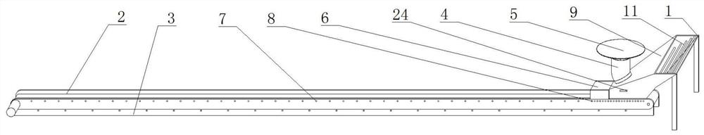
[0026] As a preferred embodiment of the present invention, the conveyor 2 includes a conveyor belt, five rollers and two motors, the five rollers are installed on both ends of the bracket through a rotating shaft, and the bolts on one side of the five rollers are installed on the two motors. On the output shaft of the conveyor belt, the conveyor belt is sleeved on the outer sides of the two drums 5, and the conveyor 2 can be opened by the switch 24, so that the top of the conveyor belt moves from right to left, and then the ore falling on the conveyor belt through the hopper is moved to the left Transportation, convenient for long-distance transportation of ore.

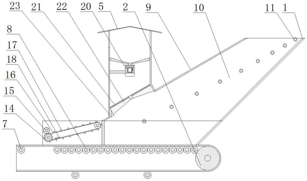
[0027]As a preferred embodiment of the present invention, the first roller 7 and the second roller 8 are installed on the support 3 through a rotating shaft, the top of one end of the conveyor belt is stuck on the top of the second roller 8, the bottom of the conveyor belt and the other The top of one side is stuck o...


PUM


Abstract

The invention provides a dustproof ore conveying device for mining. The dustproof ore conveying device comprises a hopper, a conveyor and a support. An inclined plate is welded to one side of the hopper. An air duct is welded to the inclined plate. A top cover is welded to the top of the air duct. A clamping cover is welded to the bottom of one side of the hopper. A first roller and a second roller are mounted on the support. Clamping plates are welded to the two sides of the hopper. Third rollers are mounted on the clamping plates. A supporting plate is welded to the inner wall of the top of the clamping cover. According to the dustproof ore conveying device for mining, all ore can fall to the middle of a conveyor belt, the circumstance that the falling point of the ore on the conveyor belt deviates is avoided, and the conveyor belt is prevented from deviating; small ore can be used for buffering, large ore is prevented from directly smashing the conveyor belt, and the safety of the conveyor belt and the second roller is guaranteed; and a scraper blade is used for pushing the ore, the circumstance that the conveyor belt is jammed due to the excessive ore is prevented, the operation of the conveyor belt is guaranteed, and the dustproof ore conveying device is suitable for remote conveying of the ore.

Description

technical field [0001] The invention relates to the technical field of ore conveying equipment, in particular to a dust-proof ore conveying device for mining. Background technique [0002] During ore mining operations, in order to facilitate the transportation of ore, it is necessary to use ore conveying equipment to convey the mined ore from the mining site. The patent application number is CN201310019855.4, which discloses a multi-station fully automatic ore conveying equipment. The existing ore conveying equipment basically has the advantages of long continuous working time, fast ore conveying speed, large ore conveying volume, easy maintenance and overhaul, firm structure, long service life, etc., and can meet the requirements for long-distance ore conveying. For the existing ore conveying equipment, on the one hand, when the ore is transported over a long distance, when the landing point of the ore on the conveyor belt deviates to one side, the pulling force of the conv...

Claims


Application Information

Patent Timeline
Patent Type & Authority Applications(China)
IPC IPC(8): B65G65/42B65G69/12B65G47/22B65G43/08B65G69/04B65G69/18B65G23/04B65G23/22
CPCB65G65/42B65G69/12B65G47/22B65G43/08B65G69/0416B65G69/186B65G23/04B65G23/22Y02A50/2351
Inventor 钱伟
Owner 重庆天阳矿业有限公司
Why Eureka
Try Eureka