Electric-control hydraulic special electric pole clamp

An electronically controlled hydraulic and electric pole technology, which is applied to earth movers/excavators, construction, etc., can solve problems affecting service life, equipment impact, unfavorable splitting operations, etc., to achieve improved mobility and reliable clamping force , Improve the effect of installation convenience and installation efficiency

Pending Publication Date: 2021-05-07
广西徐沃工程机械设备有限公司
View PDF0 Cites 0 Cited by
  • Summary
  • Abstract
  • Description
  • Claims
  • Application Information

AI Technical Summary

Problems solved by technology

However, currently on the market, the splitting device and the splitting main structure of the splitting machine are rigidly connected as one. When the splitting machine performs rock splitting operations, the splitting device pushes the splitting block for splitting work, resulting in hundreds of tons of The splitting force of thousands of tons is set, which will generate huge vibration to the splitting device, thereby driving the whole splitting machine to generate a certain amount of vibration, which is not conducive to the splitting operation, and will cause a great impact on the equipment and affect the service life

Method used


Image

  • Electric-control hydraulic special electric pole clamp
  • Electric-control hydraulic special electric pole clamp
  • Electric-control hydraulic special electric pole clamp

Examples


Embodiment Construction

[0021] In order to make the object, technical solution and advantages of the present invention clearer, the present invention will be described in further detail below with reference to the accompanying drawings and preferred embodiments. However, it should be noted that many of the details listed in the specification are only for readers to have a thorough understanding of one or more aspects of the present invention, and these aspects of the present invention can be implemented even without these specific details.

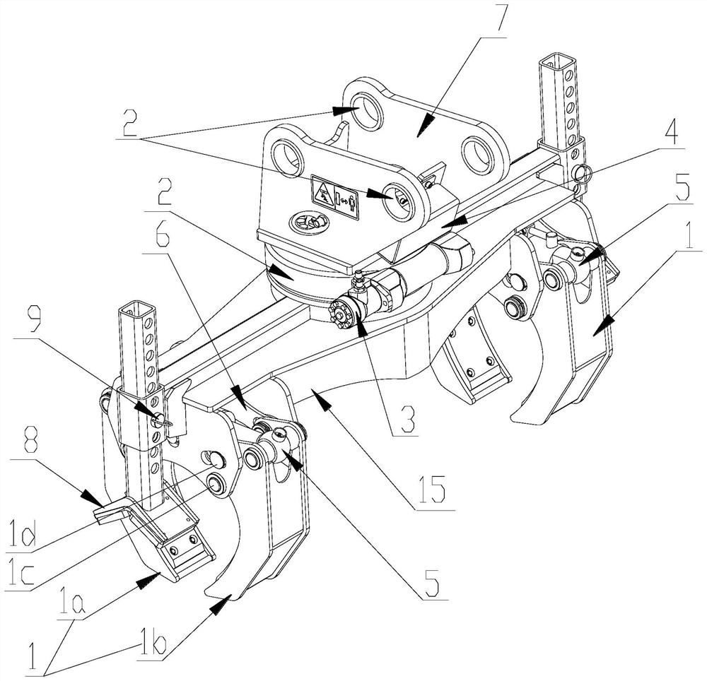
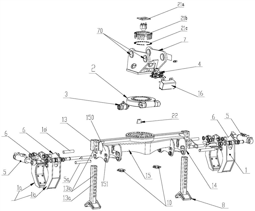
[0022] combine figure 1 , figure 2 As shown, according to a special electric pole clamp for electric control hydraulic pressure of the present invention, the electric pole clamp includes a clamping mechanism 1, a slewing bearing 2, a horse head 7 and a main frame 15, and the clamping mechanism 1 is arranged on the The two ends of the main frame 15, the slewing bearing 2 is fixed on the outer wall of the upper surface of the middle part of the main frame 15, and...


PUM


Abstract

The invention discloses an electric-control hydraulic special electric pole clamp which comprises clamping mechanisms, a rotary bearing, a swing joint and a main rack. The clamping mechanisms are arranged on the side portions of the two ends of the main rack, and the rotary bearing is fixed to the outer wall of the upper surface of the middle of the main rack. A cycloid motor for driving the rotary bearing to move forwards and backwards is fixed to the outer side of the middle of the main rack. A rotary connector is arranged at the center of the rotary bearing in a sleeved mode, and the lower end of the rotary connector is fixed to the main rack. The swing joint is fixed to the upper end of the rotary connector, an electromagnetic valve set is fixed in the swing joint, and the output end of the electromagnetic valve set is communicated with an oil inlet of the cycloid motor through an oil pipe. The electric pole clamp has high compatibility, and the electric pole installation convenience and efficiency are effectively improved.

Description

technical field [0001] The invention belongs to the technical field of power distribution overhead line operation, and in particular relates to a special electric pole clamp for electric control hydraulic pressure. Background technique [0002] With the development of economy and society, the demand for land is increasing, and mines, tunnels, and underground engineering are developing rapidly. At present, in the mining process of mine tunnels, drilling-splitting integrated tunneling equipment is used most. Especially the hydraulic splitter is an ideal non-blasting mining excavation equipment, which greatly improves the work efficiency. However, currently on the market, the splitting device and the splitting main structure of the splitting machine are rigidly connected as one. When the splitting machine performs rock splitting operations, the splitting device pushes the splitting block for splitting work, resulting in hundreds of tons of Setting a splitting force of thousand...

Claims


Application Information

Patent Timeline
Patent Type & Authority Applications(China)
IPC IPC(8): E02F9/00
CPCE02F9/00
Inventor 班华电季锐樊品珍
Owner 广西徐沃工程机械设备有限公司
Why Eureka
Try Eureka