Independent manual turning gear and turning gear structure
A manual cranking and transmission connection technology, which is applied to gas turbine devices, jet propulsion devices, engine components, etc., can solve problems such as rotor thermal bending, and achieve the effects of convenient assembly and disassembly, convenient operation and simple structure.
- Summary
- Abstract
- Description
- Claims
- Application Information
AI Technical Summary
Problems solved by technology
Method used
Image
Examples
Embodiment 1
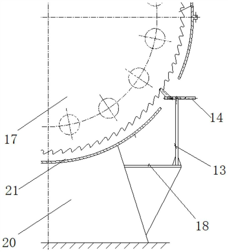
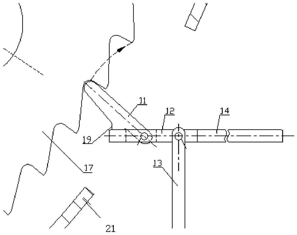
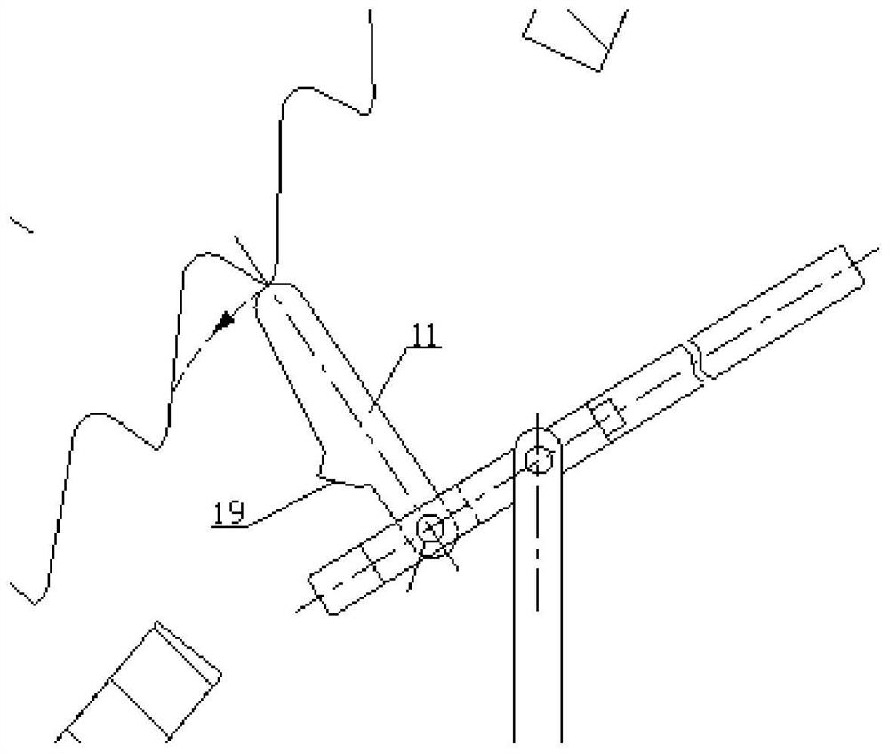
[0022] Such as figure 1 As shown, in this embodiment, an independent manual cranking device includes a support rod 13, a pressing rod 12 rotatably arranged on the support rod 13, a push rod 11 and a gear 17 rotatably arranged on the upper surface of the pressing rod 12, The center of rotation of the push rod 11 is parallel to the center of rotation of the push rod 12, the side of the push rod 11 far away from the strut 13 is provided with a boss 19 that can be in contact with the push rod 12, and the gear 17 is provided with several pieces that can be connected with the push rod 11. The teeth of the top drive link.
[0023] The barring structure includes a case support seat 20, a case 21 arranged on the case support seat 20, two rotor couplings 22 arranged in the case 21, and the gear 17 is arranged between the two rotor couplings 22 Between and in drive connection with the rotor coupling 22 , the struts 13 are arranged on the housing support base 20 and located below the sid...
Embodiment 2
[0027] On the basis of the above-mentioned embodiments, in this embodiment, the support plate 18 for supporting the strut 13 is provided on the housing support base 20 .
[0028] Utilizing the support plate 18 as the installation base of the strut 13 can improve the stability of the strut 13 and make reasonable use of the space under the casing 21 without occupying the rooting space on the foundation of the steam turbine, thereby improving the space utilization rate. The pressure generated during cranking is transmitted to the casing support seat 20, and the casing 21 will not be subjected to any pressure, thus no additional requirements are imposed on the strength of the casing 21.
[0029] In this embodiment, the support plate 18 is horizontally welded on the housing support base 20 . In this way, the connection strength between the support plate 18 and the housing support base 20 can be improved, and the stability of the support plate 18 can be improved. A diagonal brace c...
Embodiment 3
[0031] On the basis of the above embodiments, in this embodiment, an extension rod 14 is connected to the end of the pressing rod 12 away from the push rod 11 . Utilizing the extension rod 14 can conveniently control the rotation of the pressing rod 12, making the operation more convenient.
[0032] In this embodiment, the extension rod 14 is sleeved in the compression rod 12 . This facilitates the connection or disassembly of the extension bar 14 and the compression bar 12, and makes the operation more convenient when cranking is required. After the cranking is completed, it is convenient to disassemble the extension rod 14 to avoid occupying extra space, and it is convenient to uniformly manage the parts.
PUM
 Abstract
Description
Claims
Application Information
 - R&D
- Intellectual Property
- Life Sciences
- Materials
- Tech Scout
- Unparalleled Data Quality
- Higher Quality Content
- 60% Fewer Hallucinations
Browse by: Latest US Patents, China's latest patents, Technical Efficacy Thesaurus, Application Domain, Technology Topic, Popular Technical Reports.
© 2025 PatSnap. All rights reserved.Legal|Privacy policy|Modern Slavery Act Transparency Statement|Sitemap|About US| Contact US: help@patsnap.com


