Heat dissipation structure, power take-off mechanism and crane

A heat dissipation structure and crane technology, applied in mechanical equipment, transmission parts, belts/chains/gears, etc., can solve the problems of shortened service life of power transmission shafts, prolong service life, reduce possibility, and reduce temperature rise The magnitude of the effect

Inactive Publication Date: 2021-05-07
SANY AUTOMOBILE HOISTING MACHINERY
View PDF5 Cites 0 Cited by
  • Summary
  • Abstract
  • Description
  • Claims
  • Application Information

AI Technical Summary

Problems solved by technology

[0004] In order to solve the problem in the prior art that the service life of the power take-off transmission shaft is shortened after being heated, one of the purposes of the present invention is to provide a heat dissipation structure

Method used


Image

  • Heat dissipation structure, power take-off mechanism and crane
  • Heat dissipation structure, power take-off mechanism and crane
  • Heat dissipation structure, power take-off mechanism and crane

Examples


Embodiment 1

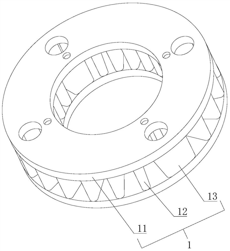
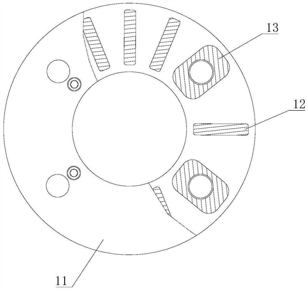
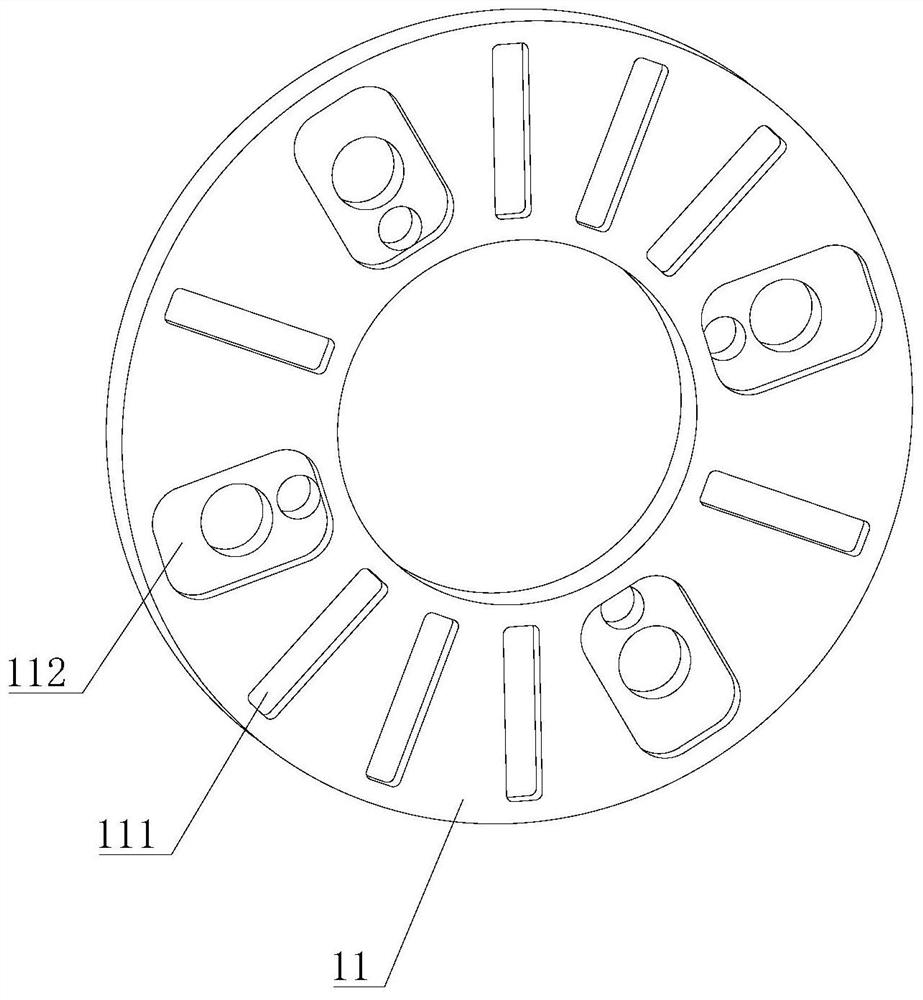
[0043] Please also refer to Figure 1 to Figure 4 , this embodiment provides a heat dissipation structure applied to a power take-off mechanism, including a heat-resistant element 1 . The heat resistance element 1 is composed of two end plates 11 and a plurality of cooling plates 12, and is connected with the power take-off device 4 and the power take-off drive shaft 5 of the power take-off mechanism.

[0044] The two end plates 11 are both ring-shaped, and the axes of the two end plates 11 coincide with the axis of the power take-off transmission shaft 5, one of the end plates 11 is connected with the power take-off 4, and the other end plate 11 is connected with the power take-off transmission shaft 5. Axis 5 is connected. The cooling plates 12 are located between the two end plates 11 , and each cooling plate 12 is perpendicular to the end plates 11 , arranged along the radial direction of the end plates 11 , and arranged along the circumferential direction of the end plat...

Embodiment 2

[0069] Please also refer to Figure 7 to Figure 9 , the difference from Embodiment 1 is that the heat dissipation structure further includes a plurality of first fan blades 2 .

[0070] Specifically, the number of first fan blades 2 is ten. Each first fan blade 2 is fixed on the outer wall of the heat-resisting element 1 , rotates with the heat-resisting element 1 , and generates an airflow along the axis of the power-taking transmission shaft 5 .

[0071] The airflow flows from the power take-off transmission shaft 5 to the power take-off 4, first passes through the cross shaft of the power take-off transmission shaft 5 towards the end of the power take-off 4, and takes away the heat on the cross shaft, then flows to the power take-off 4, and further takes away Heat on PTO 4.

[0072] After the first fan blade 2 is installed, the power take-off transmission shaft 5 is actively dissipated, so that the temperature rise of the cross shaft end covers at both ends of the power t...

Embodiment 3

[0083] see Figure 10 , the difference from Embodiment 1 is that the heat dissipation structure further includes a plurality of second fan blades 3 .

[0084] Specifically, the number of second fan blades 3 is 10, and the second fan blades 3 are fixed on the side wall of the power take-off transmission shaft 5 .

[0085] Common fixing methods include welding fixing and pin fixing. If the second fan blade 3 is fixed on the power take-off transmission shaft 5 by welding, the second fan blade 3 is not easy to disassemble and replace. If the fan blade 3 is fixed on the power take-off transmission shaft 5 , holes need to be drilled on the power take-off transmission shaft 5 , which will affect the structural strength of the power take-off transmission shaft 5 .

[0086] In order to make the second fan blade 3 easy to disassemble and avoid affecting the structural strength of the power take-off transmission shaft 5, in this embodiment, the second fan blade 3 is connected to the pow...


PUM


Abstract

The invention provides a heat dissipation structure which comprises a heat resistance part. The heat resistance part is used for connecting a power take-off device and a power take-off transmission shaft; the heat resistance part comprises two end plates and multiple heat dissipation plates; and the heat dissipation plates are arranged between the two end plates and arranged in the circumferential direction of the end plates. The invention further provides a power take-off mechanism which comprises the heat dissipation structure, the power take-off device and the power take-off transmission shaft. The invention further provides a crane which comprises the power take-off mechanism. Heat generated by the power take-off device is transmitted to the power take-off transmission shaft through the heat resistance piece, the heat resistance piece is of a hollow structure, the surface area is large, and the heat dissipation efficiency is high. The heat resistance piece and the power take-off transmission shaft rotate synchronously, so that a certain air guiding effect is achieved, and the heat dissipation effect is further improved. The heat transferred to the power take-off transmission shaft is reduced, the temperature rising amplitude of an end cover of a cross shaft is reduced, and the conditions of deformation of the end cover and softening of lubricating grease are not easy to occur, so that the possibility of dry grinding of the cross shaft is reduced, and the service life of the power take-off transmission shaft is prolonged.

Description

technical field [0001] The invention relates to the field of engineering machinery, in particular to a heat dissipation structure, a power take-off mechanism and a crane. Background technique [0002] The power take-off mechanism of the crane mainly includes a power take-off and a power take-off transmission shaft. The input shaft of the power take-off is flange-connected to the output shaft of the crane gearbox, and the output shaft of the power take-off is flange-connected to the power take-off transmission shaft. [0003] When working for a long time, the power take-off will generate a lot of heat, which will be directly transferred to the power take-off drive shaft, so that the power take-off drive shaft will be in a high temperature state for a long time. After the cross shaft end covers at both ends of the power take-off transmission shaft are heated, the lubricating grease inside the seal changes from solid to solid-liquid mixture, which affects the lubrication effect...

Claims


Application Information

Patent Timeline
Patent Type & Authority Applications(China)
IPC IPC(8): F16H57/04
CPCF16H57/0416
Inventor 沈川李光荣唐超
Owner SANY AUTOMOBILE HOISTING MACHINERY
Why Eureka
Try Eureka