Coupling structure for filter, filter and radio frequency device

A technology of coupling structure and radio frequency device, which is applied in the field of communication, can solve the problems of failure to suppress strong band-stop filter, high processing cost, poor consistency, etc.

Pending Publication Date: 2021-05-07
PROSE TECH CO LTD
View PDF1 Cites 0 Cited by
  • Summary
  • Abstract
  • Description
  • Claims
  • Application Information

AI Technical Summary

Problems solved by technology

[0002] The patent with the publication number CN106602191A discloses a high-performance band-stop filter and a communication cavity device. Specifically, it provides a band-stop filter with strong suppression, but in this patent document, a coupling plate is required to To achieve coupling, the processing cost is high, the assembly is complicated, and the consistency is poor
Therefore, this scheme does not meet the requirements of a band-stop filter with strong suppression and simple processing

Method used


Image

  • Coupling structure for filter, filter and radio frequency device
  • Coupling structure for filter, filter and radio frequency device
  • Coupling structure for filter, filter and radio frequency device

Examples


Embodiment Construction

[0036] In the following detailed description of the preferred embodiments, reference is made to the accompanying drawings which form a part of this disclosure. The accompanying drawings show, by way of example, specific embodiments in which the disclosure can be practiced. The illustrated embodiments are not intended to be exhaustive of all embodiments according to the present disclosure. It is to be understood that other embodiments may be utilized and structural or logical changes may be made without departing from the scope of the present disclosure. Accordingly, the following detailed description is not limiting, and the scope of the present disclosure is defined by the appended claims.

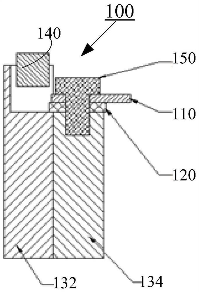
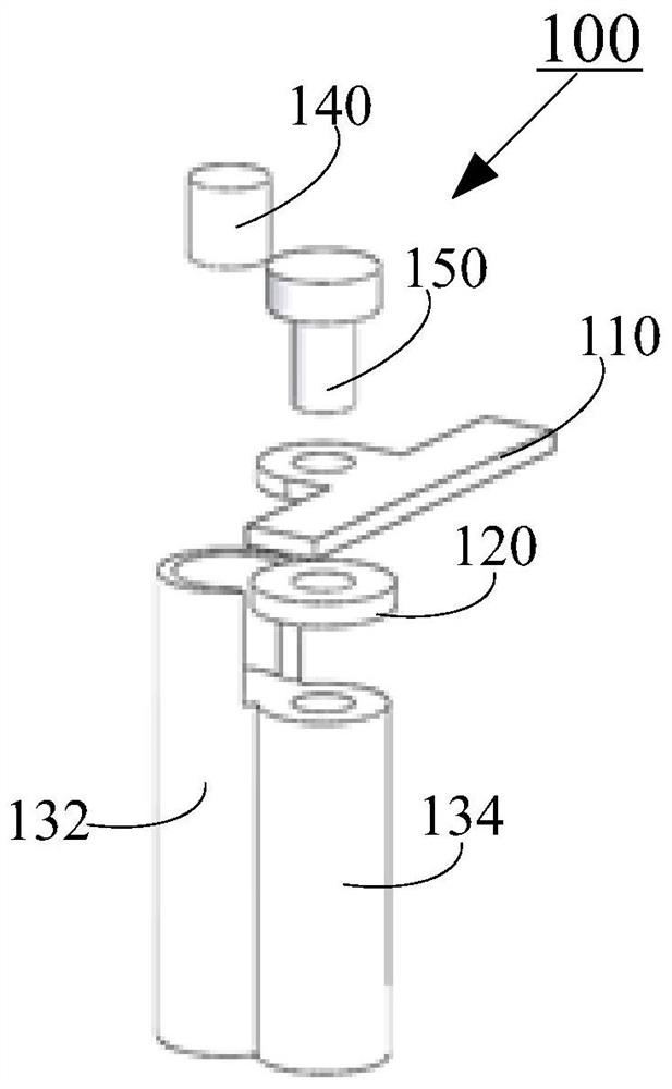
[0037] In order to solve technical problems such as poor coupling effect and insufficient suppression in the prior art, the application designs the transmission main line above a part of the resonant element, that is, above the second resonant element, and a coupling piece is arranged be...


PUM


Abstract

The invention relates to a coupling structure for a filter. The coupling structure comprises: a transmission main line, a first resonant element configured to generate a resonant frequency, a second resonant element, and a coupling piece, wherein the second resonant element is arranged side by side with the first resonant element and configured to be coupled with the transmission main line, the transmission main line is arranged at an end of the second resonant element; and the coupling piece is arranged between the transmission main line and the second resonance element so that the transmission main line and the second resonance element are not in direct contact. In the invention, the coupling piece is used to adjust the coupling between the transmission main line and the resonant element, and the transmission main line can be stably supported by means of the coupling piece. According to the coupling piece, the adjustable range is large, a coupling degree can be flexibly adjusted, and installation and debugging are convenient.

Description

technical field [0001] The present disclosure relates to the technical field of communications, and more specifically, to a coupling structure for a filter, a filter including the coupling structure, and a radio frequency device including the filter. Background technique [0002] The patent with the publication number CN106602191A discloses a high-performance band-stop filter and a communication cavity device. Specifically, it provides a band-stop filter with strong suppression, but in this patent document, a coupling plate is required to To achieve coupling, the processing cost is high, the assembly is complicated, and the consistency is poor. Therefore, this scheme does not meet the requirements of a band-stop filter with strong suppression and simple processing. Contents of the invention [0003] In view of the deep understanding of the problems in the background technology, the technical problem to be solved by the inventors of the present disclosure lies in the short...

Claims


Application Information

Patent Timeline
Patent Type & Authority Applications(China)
IPC IPC(8): H01P5/00H01P1/208
CPCH01P1/208H01P5/00
Inventor 尹泽霍永兴
Owner PROSE TECH CO LTD
Why Eureka
Try Eureka