Agricultural water conservancy irrigation equipment with water collection function

An agricultural and water collection technology, applied in the field of agriculture, can solve the problems of sedimentation growth and the reduction of water storage space inside the water collection tank, etc.

Inactive Publication Date: 2021-05-11
秦立达
View PDF0 Cites 2 Cited by
  • Summary
  • Abstract
  • Description
  • Claims
  • Application Information

AI Technical Summary

Problems solved by technology

[0003] Since the water source of the water-collecting agricultural irrigation machine usually comes from the stream canal, the plants in the stream canal easily enter the water collection tank, especially the fast-reproducing plants such as moss, which are prone to sedimentation and growth in the water collection tank, and the long-term As time grows, the water storage space inside the water collection tank will shrink

Method used


Image

  • Agricultural water conservancy irrigation equipment with water collection function
  • Agricultural water conservancy irrigation equipment with water collection function
  • Agricultural water conservancy irrigation equipment with water collection function

Examples


Embodiment 1

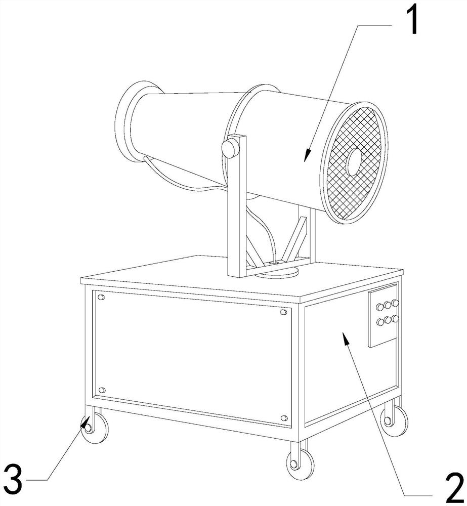
[0026] For example figure 1 -example Figure 5 Shown:

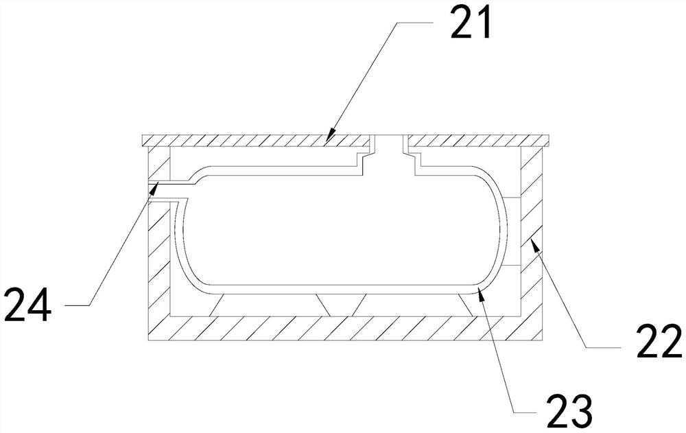
[0027] The present invention provides an agricultural water conservancy irrigation equipment with water collection, its structure includes an irrigation nozzle 1, a base 2, and a moving wheel 3, the irrigation nozzle 1 is installed on the upper end of the base 2, and the base 2 is in phase Connection; the base 2 includes an adapter plate 21, an outer frame 22, a water collection tank 23, and a water suction pipe 24, the adapter plate 21 is embedded in the upper end of the outer frame 22, and the water collection tank 23 is installed inside the outer frame 22 position, the suction pipe 24 and the water collection tank 23 are an integral structure.

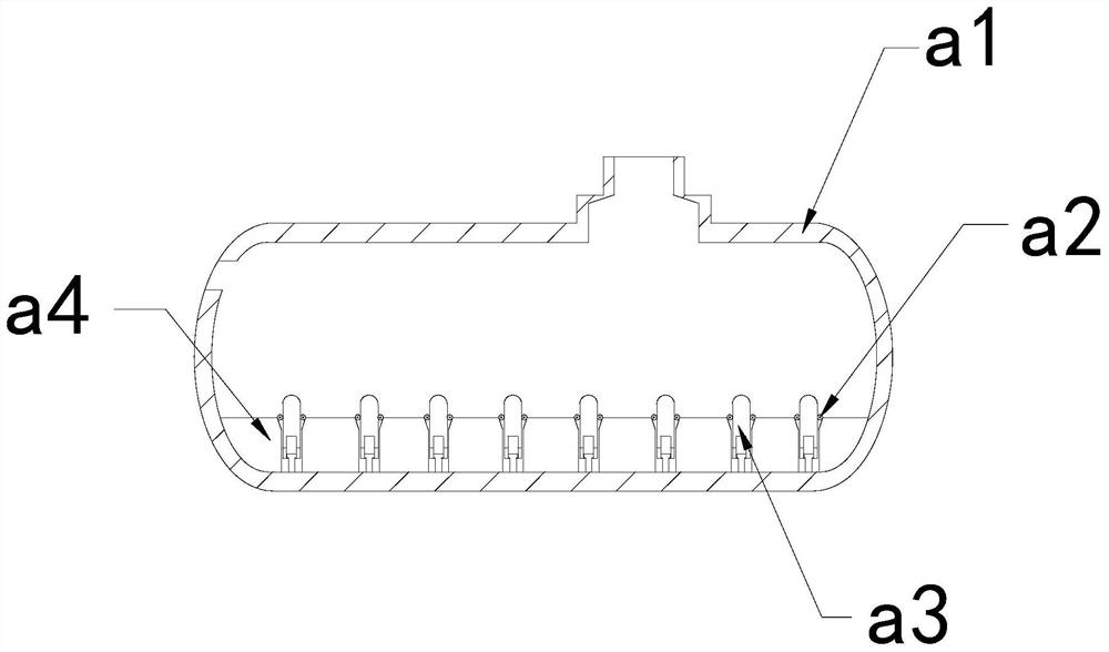
[0028] Wherein, the water collection tank 23 includes a shell a1, a blocking roller a2, an upper extension rod a3, and a fixed plate a4, the blocking roller a2 is movably engaged with the fixed plate a4, and the upper extension rod a3 is in clearance fit with the fixed plate ...

Embodiment 2

[0034] For example Figure 6 -example Figure 8 Shown:

[0035] Wherein, the intermediate connecting ring b3 includes an outer pushing plate b41, a guide frame b42, and a pull-back piece b43. The outer pushing plate b41 is movably engaged with the guide frame b42. Between the guide frames b42, the throwing force generated by the swing of the mechanism can make the outer push plate b41 protrude outward along the guide frame b42, so that the outer push plate b41 can push out most of the moss that is not attached to its inner side.

[0036] Wherein, the pusher plate b41 includes a separation block c1, a rebound piece c2, and a plate surface c3, the separation block c1 is hingedly connected with the plate surface c3, the rebound piece c2 and the separation block c1 are an integrated structure, and the separation There are ten pieces of block c1, and a group of five is evenly distributed symmetrically on the inner side of the board surface c3. The inertial force generated by the ...


PUM


Abstract

The invention discloses agricultural water conservancy irrigation equipment with a water collection function. The agricultural water conservancy irrigation equipment structurally comprises an irrigation nozzle, a base and moving wheels, the irrigation nozzle is installed at the upper end of the base, the base is connected with the moving wheels, and through thrust generated by water rushing into a shell on a stress plate, the stress plate can rotate along a combination plate under the cooperation of a rotating shaft; two outer swing plates can swing towards the two sides along a middle connecting ring through reverse thrust generated by the water on the two outer swing plates, so that cleaning grooves in the unfolded outer swing plates can scrape moss growing on the upper surface of a fixed plate under the driving of rotation of the rotating shaft; and through inertia force generated by outward extension of an outer push plate, a separation block can swing outwards along the plate surface, so that the separation block can push and remove the moss attached to the inner wall of the outer push plate, and the situation that the moss is easily attached to the inner wall of the outer push plate and is difficult to remove is effectively avoided.

Description

technical field [0001] The invention relates to the agricultural field, in particular to an agricultural water conservancy irrigation equipment with water collection. Background technique [0002] The water-collecting agricultural irrigation machine is mainly used for irrigating agricultural vegetation. The water collecting tank on the water-collecting agricultural irrigation machine can pump the water from the outside into its interior for storage, so that long-distance mobile irrigation can be realized. Based on the above description, the inventors found that the existing agricultural water irrigation equipment with water collection mainly has the following deficiencies, for example: [0003] Since the water source of the water-collecting agricultural irrigation machine usually comes from the stream canal, the plants in the stream canal easily enter the water collection tank, especially the fast-reproducing plants such as moss, which are prone to sedimentation and growth i...

Claims


Application Information

Patent Timeline
Patent Type & Authority Applications(China)
IPC IPC(8): A01G25/09
CPCA01G25/09
Inventor 秦立达
Owner 秦立达
Why Eureka
Try Eureka