
Positioning gluing device for gluing machine

The technology of a gluing device and a gluing machine, which is applied in the field of gluing, can solve problems such as the inability to move the gluing port to the position to be coated, the lack of a dust removal device and a heating device, and unsatisfactory gluing effects, so as to facilitate long-term use , Guarantee the safety of personnel and the effect of low cost

Inactive Publication Date: 2021-05-11
常州苏橡橡塑制品有限公司
View PDF6 Cites 1 Cited by
  • Summary
  • Abstract
  • Description
  • Claims
  • Application Information

AI Technical Summary

Problems solved by technology

[0002] With the rapid development of modern industry, glue applicators are used in many industries. The so-called glue applicator is a device that stores glue inside and can apply glue to the material to be coated. Compared with manual glue application, the glue applicator is much larger. It saves manpower, and is more efficient and practical. However, most of the current glue applicators lack a positioning device for glue application, and often cannot quickly and accurately move the glue application port to the position to be coated. The glue application is uneven and easy to form glue blocks. , easy to leak glue, causing material pollution, at the same time, lack of dust removal device and heating device used in conjunction, making the glue coating effect unsatisfactory

Method used


Image

  • Positioning gluing device for gluing machine
  • Positioning gluing device for gluing machine
  • Positioning gluing device for gluing machine

Examples


Embodiment Construction

[0022] The present invention will be described in further detail below in conjunction with the accompanying drawings.

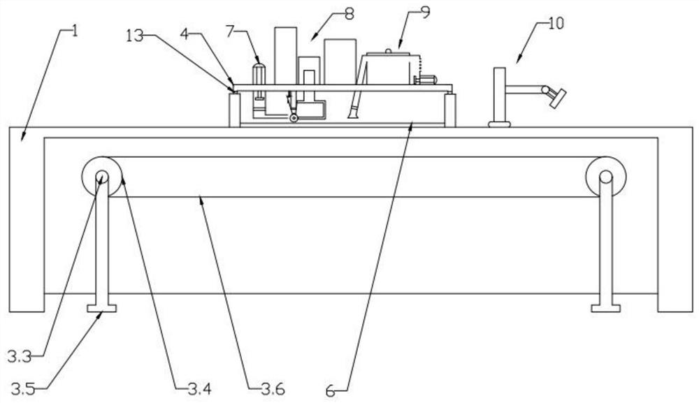
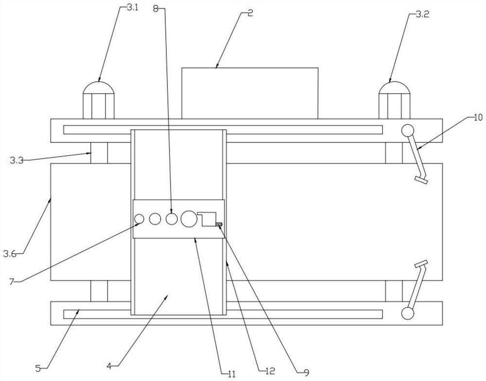
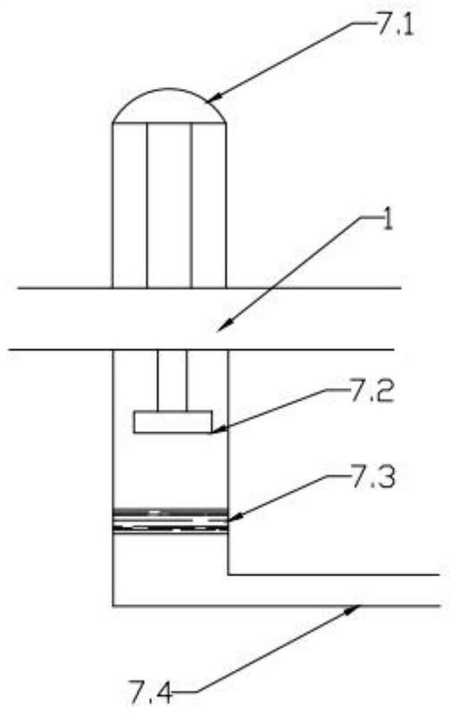
[0023] combined with figure 1 to attach Figure 8 , a positioning gluing device for a gluing machine, comprising a main frame 1, and a transport device 3 is rotated below the main frame 1, and the transport device 3 includes a screw that is fixed on the outer wall of the rear of the main frame 1 by bolts. Motor one 3.1 and motor two 3.2, the extension ends of the motor one 3.1 and motor two 3.2 are welded with a rotating shaft 3.3, the other end of the rotating shaft 3.3 is sleeved with a runner 3.4, and the outside of the runner 3.4 is provided with a conveyor belt 3.6, the other end corresponding to the rotation of the rotating shaft 3.3 is provided with a support leg 3.5, and a chute 5 is provided on the top of the main frame 1 close to the front and rear sides, and a slide plate 4 is provided for sliding on the chute 5, The bottom of the slide plate-4 i...


PUM


Abstract

The invention discloses a positioning gluing device for a gluing machine. The positioning gluing device comprises a main machine table, a conveying device is rotationally arranged below the main machine table, a first sliding groove is formed in the position, close to the front side edge and the rear side edge, of the upper face of the main machine table, a first sliding plate is arranged on the first sliding groove in a sliding mode, and a first sliding strip is integrally formed below the first sliding plate. A storage battery is fixedly arranged on the outer side wall of the rear face of the main machine table through a bolt. Second sliding grooves are formed in two sides of the first sliding plate. A second sliding plate is arranged on the second sliding grooves in a sliding manner, a sliding strip II is integrally formed below the second sliding plate, a heating device is fixedly arranged on one side of the upper face of the second sliding plate through a bolt, and a gluing device is fixedly arranged at the middle position of the second sliding plate. A secondary dust removal device is fixedly arranged on the other side of the second sliding plate through bolts, and a primary dust removal device is rotationally arranged on one side of the main machine table and located over a second motor. The positioning gluing device for the gluing machine has the beneficial effects that positioning can be achieved, gluing is even, glue leakage is avoided, and multi-structure combined work is achieved.

Description

technical field [0001] The invention relates to the technical field of gluing, in particular to a positioning gluing device for a gluing machine. Background technique [0002] With the rapid development of modern industry, glue applicators are used in many industries. The so-called glue applicator is a device that stores glue inside and can apply glue to the material to be coated. Compared with manual glue application, the glue applicator is much larger. It saves manpower, and is more efficient and practical. However, most of the current gluing machines lack positioning gluing devices, and often cannot quickly and accurately move the gluing port to the position to be coated. The gluing is uneven and easy to form gluing blocks , It is easy to leak glue, causing material pollution. At the same time, the lack of dust removal device and heating device used in conjunction makes the glue coating effect unsatisfactory. Contents of the invention [0003] In order to solve the abo...

Claims


Application Information

Patent Timeline
Patent Type & Authority Applications(China)
IPC IPC(8): B05C1/08B05C11/10B05C9/14B08B5/02B08B5/04
CPCB05C1/0813B05C11/10B05C9/14B08B5/023B08B5/043
Inventor 刘磊
Owner 常州苏橡橡塑制品有限公司
Learn More