Piezoelectric valve, fluid control device and piezoelectric valve diagnosis method

A piezoelectric valve and valve body technology, which is applied in valve devices, valve operation/release devices, semiconductor/solid-state device manufacturing, etc., can solve problems such as difficult to accurately predict the life of piezoelectric valves, improve life prediction accuracy, reduce Frequency of replacement, effect of shortening maintenance

Pending Publication Date: 2021-05-11
HORIBA STEC CO LTD
View PDF1 Cites 0 Cited by
  • Summary
  • Abstract
  • Description
  • Claims
  • Application Information

AI Technical Summary

Problems solved by technology

[0004] However, it is difficult to accurately predict the life of piezoelectric valves at present, and even if there is enough life left, the piezoelectric valve will be replaced as soon as possible.

Method used


Image

  • Piezoelectric valve, fluid control device and piezoelectric valve diagnosis method
  • Piezoelectric valve, fluid control device and piezoelectric valve diagnosis method
  • Piezoelectric valve, fluid control device and piezoelectric valve diagnosis method

Examples


Embodiment Construction

[0046] The piezoelectric valve 4 and the fluid control device 100 according to one embodiment of the present invention will be described with reference to the drawings.

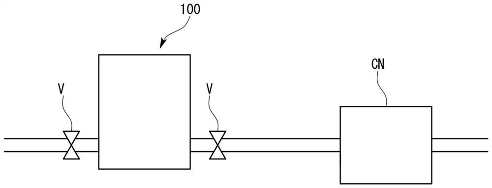
[0047] figure 1 The shown fluid control device 100 of this embodiment is a so-called mass flow controller, and is used to control, for example, the flow rate of gas supplied to a chamber. In addition, the fluid control device 100 controls fluid, and can control not only gas but also liquid as in the present embodiment.

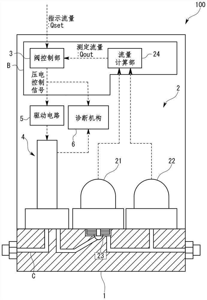
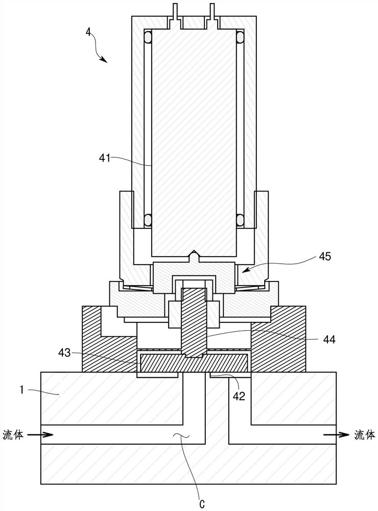
[0048] First, the fluid control device 100 will be briefly described, and then the piezoelectric valve 4 will be described in detail.

[0049] Such as figure 1 As shown, the fluid control device 100 is provided on the flow channel connected to the chamber CN, and controls the flow rate of the gas supplied to the chamber CN. In addition, in this embodiment, the on-off valves V are respectively provided on the upstream side and the downstream side of the fluid control device 100 . The gas w...


PUM


Abstract

The invention provides a piezoelectric valve, a fluid control device, and a method for diagnosing the piezoelectric valve capable of accurately predicting the lifespan of a piezoelectric actuator. The piezoelectric valve includes: a valve seat (42); a valve body (43), which is movable between a fully closed position in contact with the valve seat (42) and a fully open position; a piezoelectric actuator (41) that drives the valve body (43); a drive circuit (5) for inputting a piezoelectric control signal and outputting a drive voltage corresponding to the piezoelectric control signal to the piezoelectric actuator (41); and a leakage current detector (61) that detects a leakage current of the piezoelectric actuator (41) in a state in which the drive circuit (5) outputs a drive voltage to the piezoelectric actuator (41). The drive voltage is greater than or equal to a rated maximum voltage at which the valve body (43) is driven to the fully closed position or the fully open position. The fluid flows between the valve seat (42) and the valve body (43) in a state in which the leakage current detector (61) detects the leakage current of the piezoelectric actuator (41) or in a state just before the state.

Description

technical field [0001] The present invention relates to piezoelectric valves used, for example, in semiconductor manufacturing processes. Background technique [0002] In the semiconductor manufacturing process, in order to control the flow rate and pressure of process gas at high speed, piezoelectric valves with piezoelectric actuators with excellent responsiveness are used. For example, in an ALD (Atomic Layer Deposition) process, high-speed switching of a piezoelectric valve is repeatedly performed to form a layer of one atom (see Patent Document 1). [0003] If the piezoelectric valve continues to be used, for example, the piezoelectric actuator is gradually damaged and deteriorated due to the above-mentioned operation, which may cause failure. Therefore, in order to ensure accurate flow and pressure control, it is desirable to be able to accurately predict the period of complete failure. [0004] However, at present, it is difficult to accurately predict the lifetime ...

Claims


Application Information

Patent Timeline
Patent Type & Authority Applications(China)
IPC IPC(8): F16K31/04F16K37/00G01R31/52
CPCF16K31/04F16K37/00F16K37/0025F16K37/005G01R31/52F16K37/0041F16K31/007F16K1/00F16K31/004F16K31/02H01L21/67017F16K1/32
Inventor 杰弗里·兰斯德尔
Owner HORIBA STEC CO LTD
Why Eureka
Try Eureka