
Pneumatic training gun pneumatic mechanism

A training gun and pneumatic technology, which is applied in the field of firearms training equipment, can solve the problems of safety hazards of blank bullet training guns and the lack of mature products.

Pending Publication Date: 2021-05-11
CHONGQING JIANSHE IND GRP
View PDF0 Cites 0 Cited by
  • Summary
  • Abstract
  • Description
  • Claims
  • Application Information

AI Technical Summary

Problems solved by technology

[0002] At present, individual weapons and equipment training methods are diversified, and individual tactical training is getting more and more attention. Various training methods such as indoor confrontation training and VR simulation training are rapidly emerging, and special requirements are put forward for various training equipment. Firearms are required to be safe and reliable, with a high degree of simulation. Due to their special use environment, the existing empty ammunition training guns have greater safety hazards. Pneumatic and electric training guns and their training systems are gradually entering the military and armed police , Public Security Colleges, pneumatic training guns are widely loved by students for their safety, reliability and high degree of simulation, but there are no mature products for the majority of students to use, so it is necessary to develop a pneumatic mechanism suitable for pneumatic training guns

Method used


Image

  • Pneumatic training gun pneumatic mechanism
  • Pneumatic training gun pneumatic mechanism
  • Pneumatic training gun pneumatic mechanism

Examples


Embodiment Construction

[0025] Embodiments of the present invention will be described in further detail below in conjunction with the accompanying drawings.

[0026] The present invention takes the firearm shooting direction as the front.

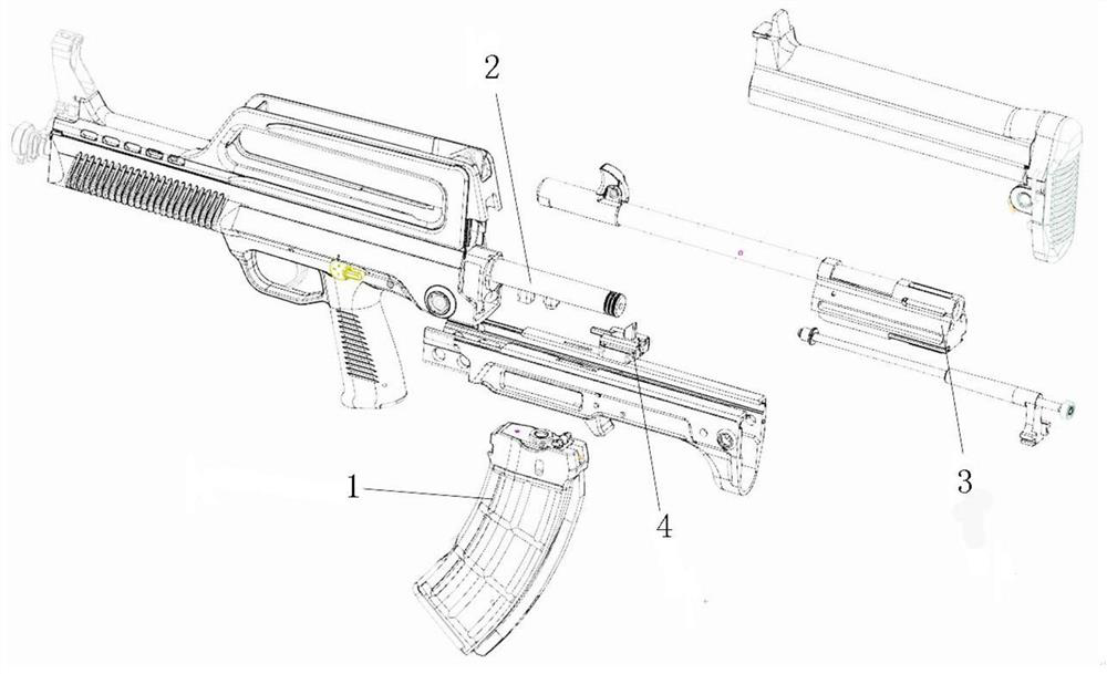
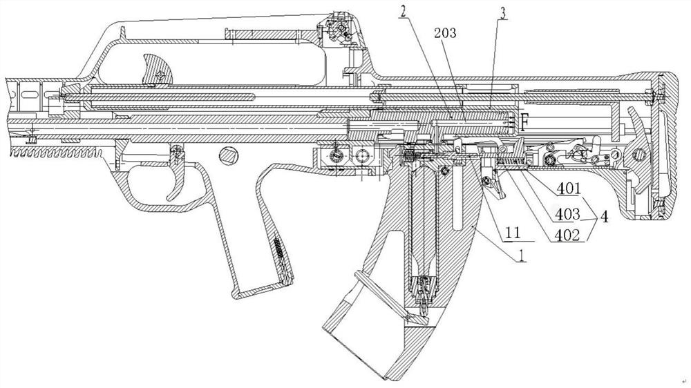
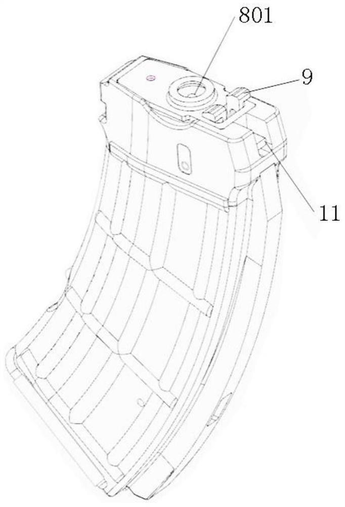
[0027] see Figure 1-Figure 7 , a pneumatic mechanism for a pneumatic training gun, comprising a magazine 1, a cylinder 2, a body seat 3 and an air valve strike mechanism 4, the magazine 1 is clamped at the magazine interface of the pneumatic training gun, and the magazine 1 is provided with a gas Valve gas storage and deflation mechanism, used to seal the CO in the magazine 1 2 High-pressure gas and delayed deflation, the top of the magazine 1 is provided with an air outlet 801, and the bottom of the cylinder 2 is provided with an air inlet 201, opposite to the air outlet 801 of the magazine, the CO released in the magazine 1 2 The high-pressure gas enters the cylinder 2 from the cylinder air inlet 201 through the magazine outlet hole 801, and the cylinder 2 is...


PUM


Abstract

The invention discloses a pneumatic training gun pneumatic mechanism. The pneumatic training gun pneumatic mechanism comprises a magazine, an air cylinder, a machine body base and an air valve striking mechanism, the magazine is clamped to a magazine connector, an air valve air storage and deflation mechanism is arranged in the magazine, an air outlet is formed in the top of the magazine, and an air inlet is formed in the bottom of the air cylinder and is opposite to the air outlet of the magazine. High-pressure gas released in the magazine enters the air cylinder from an air cylinder air inlet through the air outlet of the magazine, a gas sealing ring groove used for sealing a gap between the air cylinder and the machine body base is further formed in the rear end of the air cylinder, the machine body base sleeves the air cylinder, and an expansion chamber in the axial direction is arranged at the rear end of the machine body base, and a piston mechanism is formed between the air cylinder and the expansion chamber of the machine body base. Convex ribs are arranged at the bottom of the machine body base in the axial direction and used for controlling the deflation time of the high-pressure gas in the magazine, and the air valve striking mechanism is installed in a pneumatic training gun case and used for striking the air valve air storage and deflation mechanism in the magazine to achieve magazine deflation. A pneumatic training gun of the pneumatic training gun pneumatic mechanism is consistent with a real gun, has the same operation method, and has the advantages of simple structure, safety, reliability, high simulation degree and the like.

Description

technical field [0001] The invention belongs to the technical field of firearm training equipment, and relates to a pneumatic mechanism of a pneumatic training gun. Background technique [0002] At present, individual weapon equipment training methods are diversified, and individual tactical training is getting more and more attention. Various training methods such as indoor confrontation training and VR simulation training are rapidly emerging, and special requirements are put forward for various training equipment. Firearms are required to be safe and reliable, with a high degree of simulation. Due to their special use environment, the existing empty ammunition training guns have greater safety hazards. Pneumatic and electric training guns and their training systems are gradually entering the military and armed police , Public Security Colleges, pneumatic training guns are widely loved by students for their safety, reliability and high degree of simulation, but there are c...

Claims


Application Information

Patent Timeline
Patent Type & Authority Applications(China)
IPC IPC(8): F41A33/00F41A33/06F41A9/61
CPCF41A33/00F41A9/61F41A33/06
Inventor 何志勇侯洪章谌炳军徐雅文胡金鹏袁凯马永逸徐剑锋
Owner CHONGQING JIANSHE IND GRP
Learn More