Radial compensation method and device for VSP variable offset wave field acquired by DAS

A compensation method and a technology of variable offset distance, which are applied in the direction of measuring devices, instruments, scientific instruments, etc., can solve the problems of inability to achieve effective radial compensation and correction of the wave field of optical fiber acquisition data, and achieve the effect of improving the amplitude preservation effect

Active Publication Date: 2021-05-11
OPTICAL SCI & TECH (CHENGDU) LTD
View PDF10 Cites 0 Cited by
  • Summary
  • Abstract
  • Description
  • Claims
  • Application Information

AI Technical Summary

Problems solved by technology

Conventional three-component geophones are generally used for VSP acquisition in existing borehole seismic. When the offset changes, the space vector wave field is recorded by the X, Y, and Z three-component geophones in the Cartesian coordinate system, which can be processed by vector rotation synthesis. Synthesize scalar wave field vectors collected on different components into the spatial radial direction of the actual wave field; since DAS VSP can only perform single-component acquisition at present, unlike conventional three-component detectors, it can only respond to scalar waves along the direction of the fiber field, when the offset changes, due to the lack of other component information of the space coordinate system, the conventional vector rotation synthesis processing method cannot be used to correct the actual radial wave field, so the existing vector rotation synthesis processing method is only suitable for the three-component conventional The detector cannot realize the effective radial compensation of the wave field of the DAS VSP optical fiber acquisition data

Method used


Image

  • Radial compensation method and device for VSP variable offset wave field acquired by DAS
  • Radial compensation method and device for VSP variable offset wave field acquired by DAS
  • Radial compensation method and device for VSP variable offset wave field acquired by DAS

Examples


Embodiment Construction

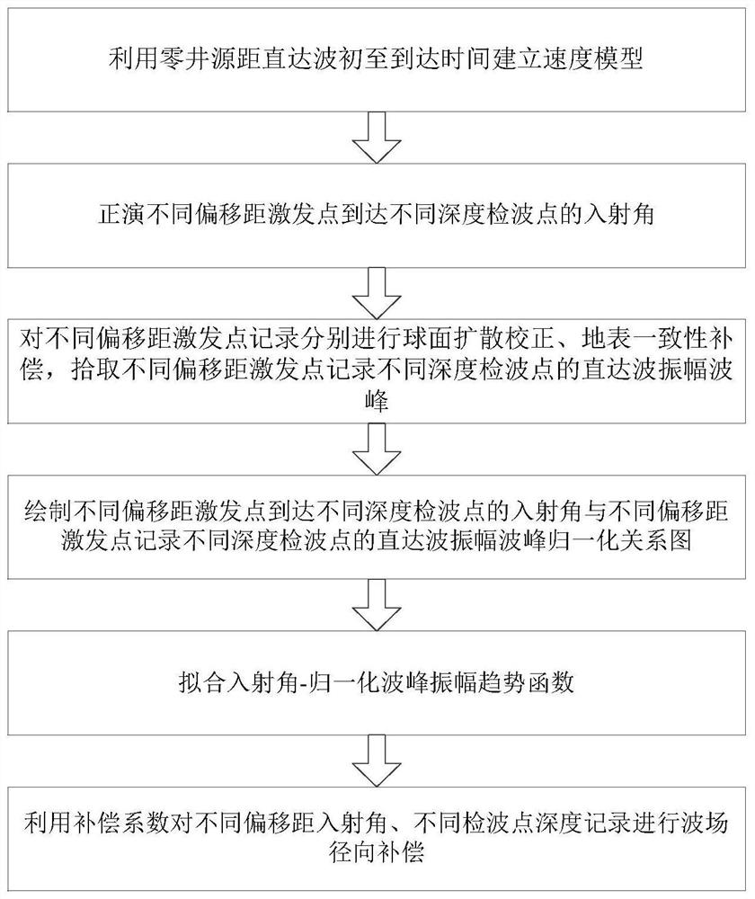
[0031] The technical solution of the present invention will be further described in detail below in conjunction with the accompanying drawings, but the protection scope of the present invention is not limited to the following description.

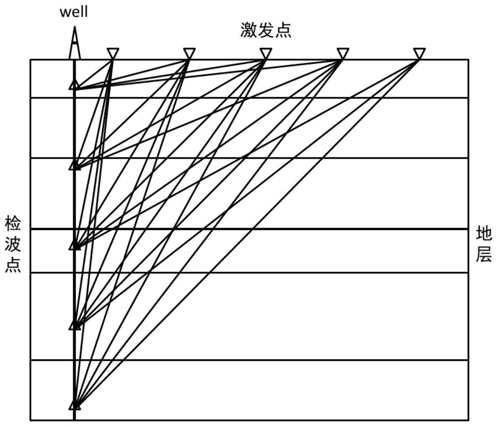
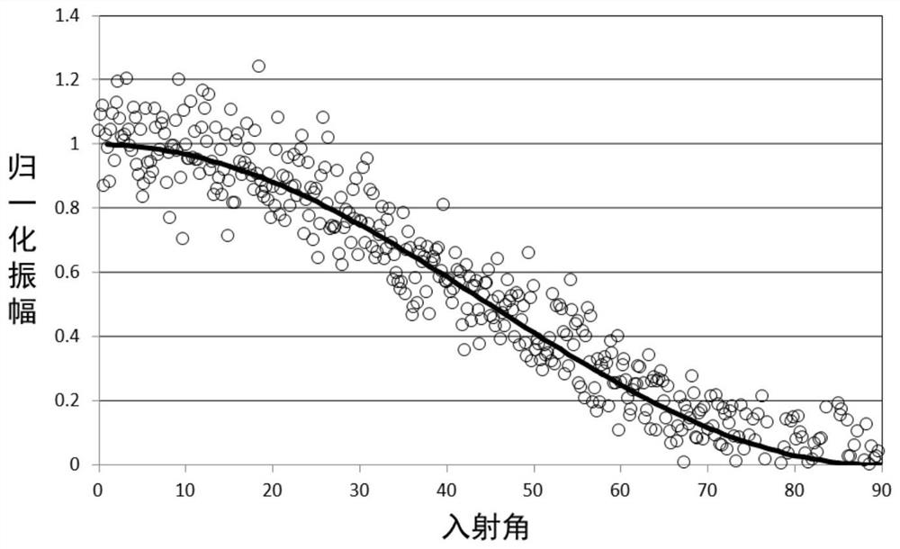
[0032] The present invention considers that the conventional three-component detector can only respond to the scalar wave field along the direction of the optical fiber. When the offset changes, due to the lack of other component information of the space coordinate system, the actual diameter cannot be analyzed by the conventional vector rotation synthesis processing method. In addition, as the offset increases, the attenuation law of the direct wave field collected by DAS-VSP is also different from the Z component collected by the conventional three-component geophone. The direct wave field collected by the conventional three-component geophone The Z-component record is proportional to the cosine of the incident angle, and the direct wavefi...


PUM


Abstract

The invention discloses a radial compensation method and device for a VSP variable offset wave field acquired by a DAS. The method comprises the following steps: S1, establishing a speed model by using zero well distance direct wave first arrival time; S2, forward modeling incident angles of different offset excitation points to different depth detection points; S3, respectively carrying out spherical diffusion correction and earth surface consistency compensation on different offset excitation point records, picking up the different offset excitation points, and recording direct wave amplitude wave crests of different depth detection points; S4, drawing a normalized relational graph of incidence angles of different offset excitation points to different depth detection points and direct wave amplitude wave crests of different depth detection points recorded by different offset excitation points; S5, fitting an incident angle-normalized wave crest amplitude trend function; and S6, carrying out wave field radial compensation on different offset incident angles and different detection point depth records by utilizing a compensation coefficient. The provided wave field radial compensation method is suitable for DAS VSP optical fiber acquisition data, meets the wave field propagation law, and improves the amplitude preservation effect of recording the wave field in the processing process.

Description

technical field [0001] The invention relates to the processing and correction of the seismic VSP data wave field in a variable offset well, in particular to a radial compensation method and device for the VSP variable offset wave field acquired by a DAS. Background technique [0002] Distributed optical fiber sensing in-well geophysics technology is a new technology in well-bore geophysics emerging in recent years. With the continuous progress of Distributed Optical Fiber Acoustic Sensing (DAS for short), DAS has achieved certain results in the fields of border security, oil and gas pipeline monitoring, geological disaster prediction, and engineering tunnel bridge monitoring. The application of sensing well seismic (DAS VSP) is also gradually mature, and is expanding towards the application direction of hydraulic fracturing microseismic monitoring, oil field temperature and pressure, long-term monitoring of stress and strain, etc. [0003] Optical fiber geophysical technolo...

Claims


Application Information

Patent Timeline
Patent Type & Authority Applications(China)
IPC IPC(8): G01V1/36G01V1/28G01V1/40
CPCG01V1/362G01V1/282G01V1/28G01V1/40G01V2210/51
Inventor 李飞刘聪伟王雪峰金其虎李建国吴俊军
Owner OPTICAL SCI & TECH (CHENGDU) LTD
Why Eureka
Try Eureka