
MEMS scanning mirror and laser projector

A technology for scanning mirrors and mirrors, which is applied in the field of laser projection, can solve the problems of the mirror 10 being hindered in rotation and difficult to accurately drive the mirror 10, and achieve the effects of miniaturization, precision improvement, and driving

Active Publication Date: 2021-05-11
GOERTEK INC
View PDF15 Cites 0 Cited by
  • Summary
  • Abstract
  • Description
  • Claims
  • Application Information

AI Technical Summary

Problems solved by technology

However, this method will hinder the rotation of the mirror 10, and it is difficult to accurately drive the mirror 10 when following the resonant frequency.

Method used


Image

  • MEMS scanning mirror and laser projector
  • MEMS scanning mirror and laser projector
  • MEMS scanning mirror and laser projector

Examples


Embodiment Construction

[0027] In order to illustrate the present invention more clearly, the present invention will be further described below in conjunction with preferred embodiments and accompanying drawings. Similar parts in the figures are denoted by the same reference numerals. Those skilled in the art should understand that the content specifically described below is illustrative rather than restrictive, and should not limit the protection scope of the present invention.

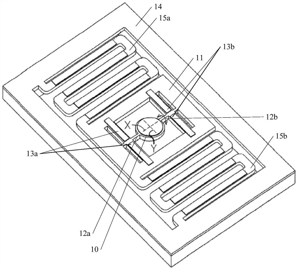
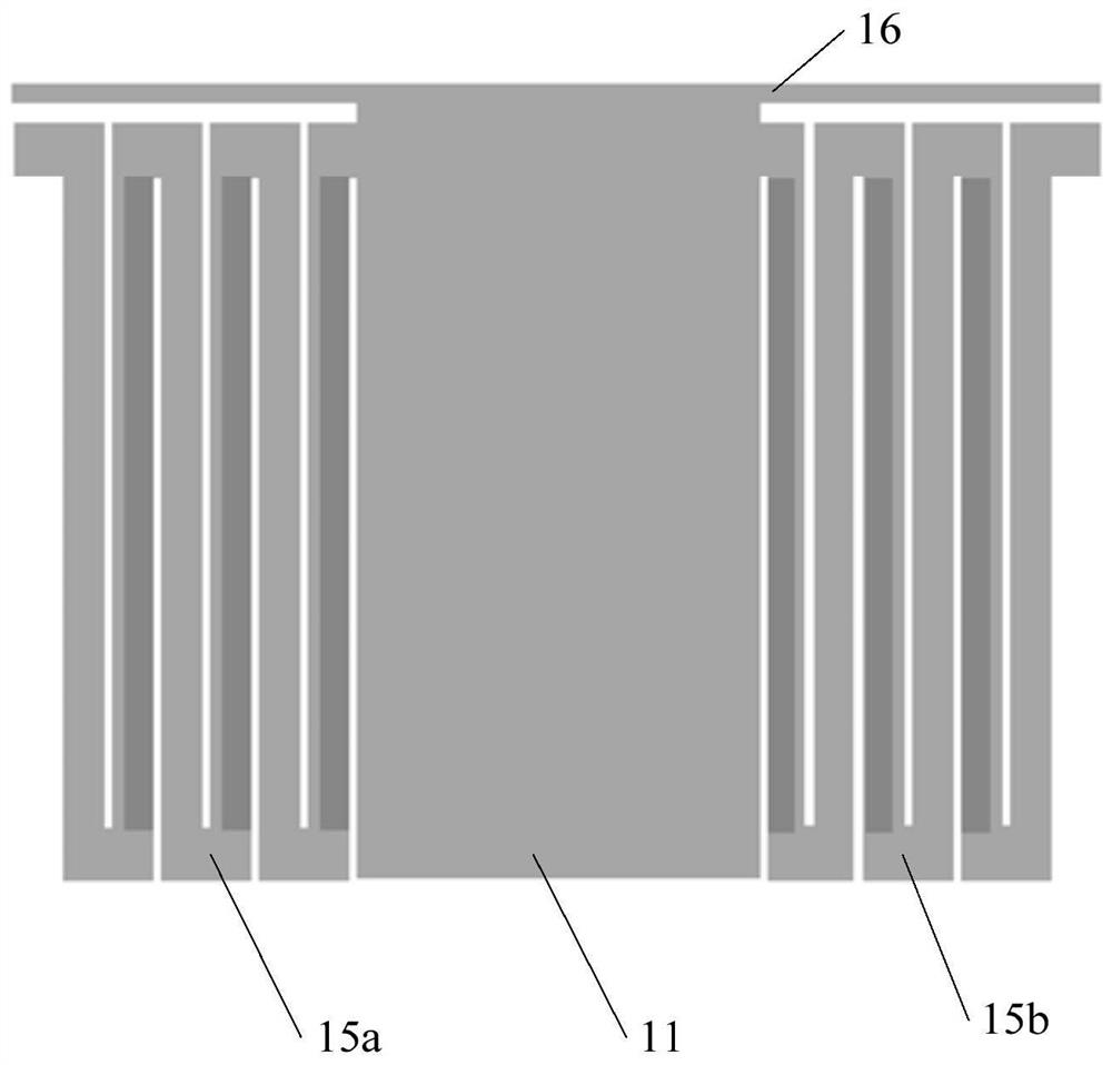
[0028] One embodiment of the present invention provides a MEMS scanning mirror, including a support, a mirror, and a first piezoelectric actuator and a second piezoelectric actuator respectively used as a cantilever, the first piezoelectric actuator The device and the second piezoelectric actuator are used to rotate the mirror around the first rotation axis, and the MEMS scanning mirror also includes a first sensing beam, one end of the first sensing beam is connected to the support, and the other end Connecting to one sid...


PUM


Abstract

The invention discloses an MEMS scanning mirror and a laser projector. According to one specific embodiment, the MEMS scanning mirror comprises a supporting piece, a reflecting mirror, a first piezoelectric actuator, a second piezoelectric actuator and a first sensing beam. The first piezoelectric actuator and the second piezoelectric actuator serve as cantilevers respectively, the first piezoelectric actuator and the second piezoelectric actuator are used for enabling the reflecting mirror to rotate around a first rotating shaft, one end of the first sensing beam is connected with the supporting piece, the other end of the first sensing beam is connected with one side of the reflecting mirror, and a first angle sensor used for sensing the deflection angle of the reflecting mirror rotating around the first rotating shaft is arranged on the first sensing beam. According to the embodiment of the invention, the rotation of the reflecting mirror can be prevented from being hindered, the detection precision of the deflection angle of the reflecting mirror is improved, and the miniaturization of the MEMS scanning mirror is facilitated.

Description

technical field [0001] The invention relates to the technical field of laser projection. More specifically, it relates to a MEMS scanning mirror and a laser projector. Background technique [0002] A laser projector using a MEMS (Micro Electro Mechanical System, Micro Electro Mechanical System) scanning mirror has the advantages of low cost and miniaturization, and has a broad market prospect. [0003] Traditional MEMS scanning mirrors often use torsion bar actuation. The mirror is tilted and twisted by two, three or more torsion bars supporting the mirror to perform optical scanning. Resonant drive is used to achieve large scanning Angle, it is necessary to match the resonant frequency of the tilting motion of the mirror with the driving frequency through structural design. [0004] When driving the MEMS scanning mirror or monitoring the mirror angle, in order to maintain the resonance state, the current method is to set an angle sensor for sensing the deflection angle of...

Claims


Application Information

Patent Timeline
IPC IPC(8): G02B26/08G02B26/10G02B26/12
CPCG02B26/0858G02B26/101G02B26/127
Inventor 林育菁畠山庸平
Owner GOERTEK INC
Learn More