Near-eye optical system

An optical system, near-eye technology, applied in the field of optical systems, can solve problems such as limitations and inability to meet demands, and achieve the effect of expanding the viewing angle range

Active Publication Date: 2021-05-11
CORETRONIC
View PDF8 Cites 1 Cited by
  • Summary
  • Abstract
  • Description
  • Claims
  • Application Information

AI Technical Summary

Problems solved by technology

When a waveguide is used to transmit image beams, the field of view is mainly affected by the material and form factor of the waveguide. Therefore, the field of view that the conventional waveguide can provide is limited and cannot meet the demand.

Method used


Image

  • Near-eye optical system
  • Near-eye optical system
  • Near-eye optical system

Examples


Embodiment Construction

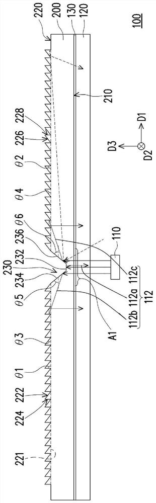
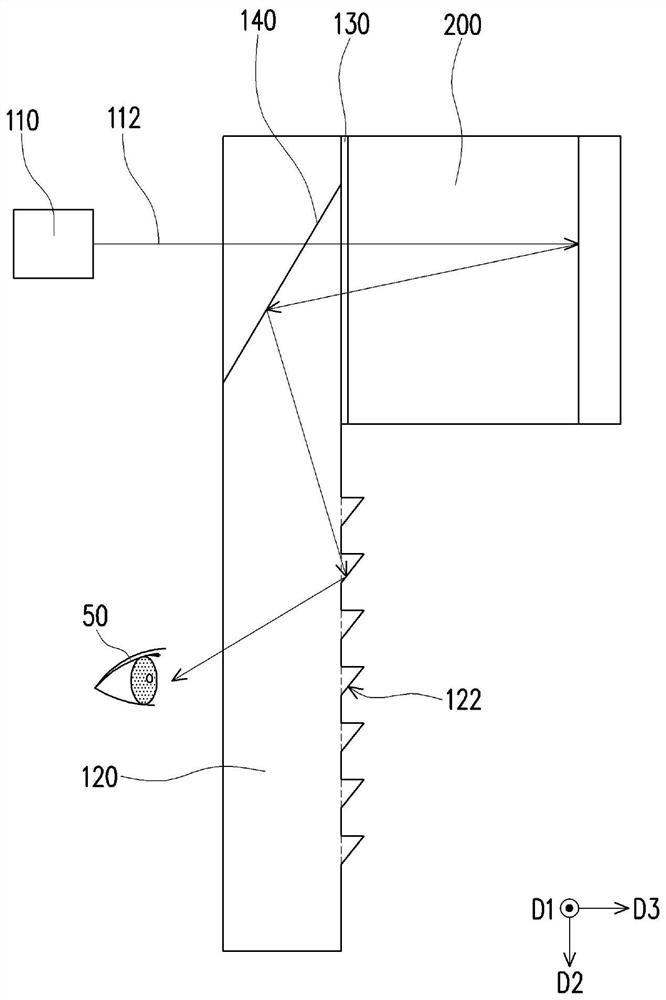
[0011] Figure 1A and Figure 1B It is a schematic cross-sectional view of a near-eye optical system in two different directions according to an embodiment of the present invention. Please refer to Figure 1A and Figure 1B The near-eye optical system 100 of this embodiment is used to receive an image beam 112, and the image beam 112 is emitted by a projector 110, for example, and the projector 110 is, for example, a picoprojector. The near-eye optical system 100 includes a first optical waveguide 200 for expanding the image beam 112 in the first direction D1. The first optical waveguide 200 includes a first surface 210, a second surface 220, a plurality of first reflective slopes 222 and a plurality of A second reflective slope 226. The first surface 210 has a first light incident area A1 , and the second surface 220 is opposite to the first surface 210 . The second surface 220 has a recessed area 230 aligned with and corresponding to the first light incident area A1. The...


PUM


Abstract

A near-to-eye optical system is used for receiving an image light beam, and comprises a first optical waveguide which is used for expanding the image light beam in a first direction and comprises a first surface, a second surface, a plurality of first reflection inclined planes and a plurality of second reflection inclined planes. The first surface has a first light incident area, and the second surface is opposite to the first surface. The second surface is provided with a concave area, the concave area is aligned with the first light incident area, and the concave area is provided with a flat bottom face, a first inclined side wall and a second inclined side wall, the first reflection slopes are arranged on the second surface, and the second reflection slopes are arranged on the second surface. The first reflection inclined planes, the recessed area and the second reflection inclined planes are sequentially arranged along a first direction, and the first inclined side wall, the flatbottom surface and the second inclined side wall are sequentially arranged along the first direction. The near-to-eye optical system can effectively expand the visual angle range, and has high light efficiency and high image uniformity.

Description

technical field [0001] The present invention relates to an optical system, and in particular to a near-eye optical system. Background technique [0002] The history of near-eye optical systems such as head-mounted displays HMD (Head / Helmet-mounted displays, HMDs) can be traced back to the US military in the 1970s. A projection device is used to project the image or text information on the display component into the eyes of the user. [0003] In recent years, with the development of micro-display components: the growth trend of higher and higher resolution, smaller size, and smaller power consumption, and the development of cloud technology: a large amount of information can be downloaded from the cloud anytime, anywhere, without the need for a huge The hassle of carrying your database with you. The near-eye optical system has been developed into a portable display device. In addition to the military field, other related fields such as industrial production, simulation tra...

Claims


Application Information

Patent Timeline
Patent Type & Authority Applications(China)
IPC IPC(8): G02B27/01
CPCG02B27/0172G02B2027/0123G02B27/283
Inventor 简宏达
Owner CORETRONIC
Why Eureka
Try Eureka