Automatic lamination device of distribution transformer

A technology for distribution transformers and lamination devices, which can be used in inductor/transformer/magnet manufacturing, circuits, electrical components, etc., and can solve problems such as low work efficiency

Active Publication Date: 2021-05-11
晋中益电变压器有限公司
View PDF6 Cites 5 Cited by
  • Summary
  • Abstract
  • Description
  • Claims
  • Application Information

AI Technical Summary

Problems solved by technology

[0005] In order to overcome the shortcomings of stacking iron cores that are generally operated by two people, which require a lot of manpower and low work efficiency, the technical problem to be solved is: to provide an automatic stacking and reduce a lot of manpower. Electric transformer automatic lamination device

Method used


Image

  • Automatic lamination device of distribution transformer
  • Automatic lamination device of distribution transformer
  • Automatic lamination device of distribution transformer

Examples


Embodiment 1

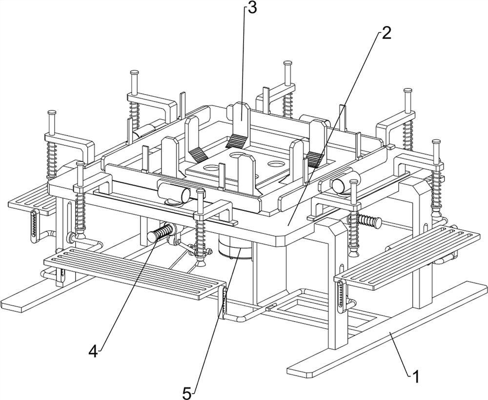
[0028] Such as figure 1 As shown, an automatic stacking device for a distribution transformer includes a bottom plate 1, a first support plate 2, a limit mechanism 3, a transmission mechanism 4 and a drive mechanism 5, the bottom plate 1 is provided with a first support plate 2, the first A limit mechanism 3 is provided on the support plate 2 , a transmission mechanism 4 is provided at the bottom of the first support plate 2 , and a drive mechanism 5 is provided on the bottom plate 1 , and the drive mechanism 5 cooperates with the transmission mechanism 4 .

[0029] When it is necessary to stack the iron cores of the distribution transformer, the staff places the iron cores on the first support plate 2 between the limit mechanism 3, and then the staff starts the driving mechanism 5, and the driving mechanism 5 rotates to drive the transmission mechanism 4 Rotate, the transmission mechanism 4 rotates and drives the limit mechanism 3 to slide towards each other to stack the iron...

Embodiment 2

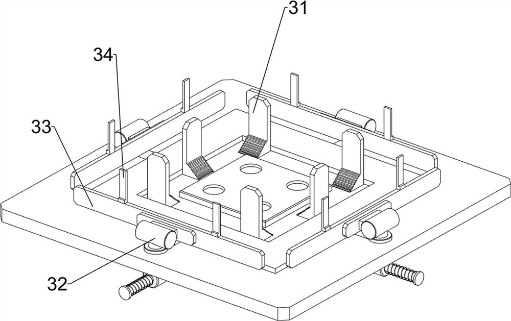
[0031] Such as figure 2 , image 3 and Figure 4 As shown, on the basis of Embodiment 1, the limit mechanism 3 includes a baffle plate 31, a first slider 32, a first fixed block 33 and a first fixed rod 34, and the middle part of the first support plate 2 is evenly spaced Six baffles 31, the four sides of the first support plate 2 are provided with chute, the first slider 32 is slidably arranged in the four chute, and the opposite side of the four first slider 32 is provided with the first fixed Block 33 , first fixing rods 34 are symmetrically arranged on the four first fixing blocks 33 .

[0032] When it is necessary to stack the iron cores of the distribution transformer, the staff places the iron cores on the first support plate 2 between the first fixing block 33 and the baffle plate 31, and then the staff starts the driving mechanism 5, and the driving mechanism 5 The rotation drives the transmission mechanism 4 to rotate, and the rotation of the transmission mechani...

Embodiment 3

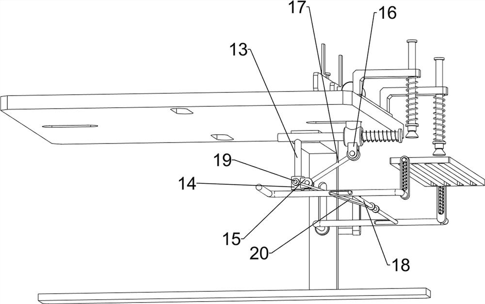
[0038] Such as Figure 5 , Figure 6 and Figure 7 As shown, it also includes a second slider 6, a third fixed rod 7, a second straight chute plate 8, a first guide rod 9, a third slider 10, a second support plate 11 and a second elastic member 12 , the bottom plate 1 is provided with two inline chutes on the front and rear sides, the four inline chutes are all slidingly provided with a second slider 6, and the four second sliders 6 are all provided with a third fixing rod 7 , the two ends of the four third fixed rods 7 are provided with the second straight chute plate 8, each second straight chute plate 8 is provided with the first guide rod 9, each first guide rod 9 The third sliding block 10 is provided in a sliding manner, and a second support plate 11 is arranged between the two third sliding blocks 10 on the same side. One side of each third sliding block 10 is connected to each second straight chute. A second elastic member 12 is arranged between one side of the boar...


PUM


Abstract

The invention relates to an automatic lamination device, and especially relates to an automatic lamination device for a distribution transformer. The invention provides the automatic lamination device for the distribution transformer, which can be used for automatically laminating and reducing a large amount of manpower. The automatic lamination device for the distribution transformer comprises: a bottom plate provided with a first supporting plate; a limiting mechanism arranged on the first supporting plate; a transmission mechanism arranged at the bottom of the first supporting plate; and a driving mechanism arranged on the bottom plate, wherein the driving mechanism is matched with the transmission mechanism. The driving mechanism rotates to drive the transmission mechanism to rotate, and the transmission mechanism rotates to drive the limiting mechanism to slide oppositely to stack the iron cores.

Description

technical field [0001] The invention relates to an automatic lamination device, in particular to an automatic lamination device for a distribution transformer. Background technique [0002] Distribution power transformer is a kind of static electrical equipment, which is used to change the AC voltage of a certain value into another voltage with the same frequency or several different values. When the primary winding is supplied with alternating current, alternating magnetic flux will be generated, and the alternating magnetic flux will induce an alternating electromotive force in the secondary winding through the magnetic conduction of the iron core. [0003] In the process of processing distribution transformers, the iron cores need to be stacked in the order of center, left, and right. However, this stacking method is generally operated by two people, which requires a lot of work. Manpower, low work efficiency. [0004] Therefore, it is necessary to design an automatic s...

Claims


Application Information

Patent Timeline
Patent Type & Authority Applications(China)
IPC IPC(8): H01F41/02
CPCH01F41/0233
Inventor 刘正奥
Owner 晋中益电变压器有限公司
Why Eureka
Try Eureka