Enameled wire hot wax automatic coating device

An automatic coating and enameled wire technology, which is applied in the field of enameled wires, can solve the problems of uneven coating, lower temperature, and lower fluidity of adsorption felts, and achieve the effect of accelerating air circulation

Pending Publication Date: 2021-05-14
湖北首通电磁线科技股份有限公司
View PDF1 Cites 0 Cited by
  • Summary
  • Abstract
  • Description
  • Claims
  • Application Information

AI Technical Summary

Problems solved by technology

[0004] 1. When the atomized paraffin wax is sprayed on the adsorption felt, the temperature of the paraffin wax on the inner wall of the adsorption felt will be relatively lower, so that the outer layer of the paraffin wax will be solidified, which will greatly reduce its fluidity on the adsorption felt, and even block the felt. , can not normally carry out the coating work
[0005] 2. Because traditional devices are often unable to coat enameled wires of different diameters, and are prone to uneven coating, it is difficult to control the quality of finished products

Method used


Image

  • Enameled wire hot wax automatic coating device
  • Enameled wire hot wax automatic coating device
  • Enameled wire hot wax automatic coating device

Examples


Embodiment 1

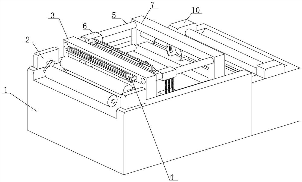
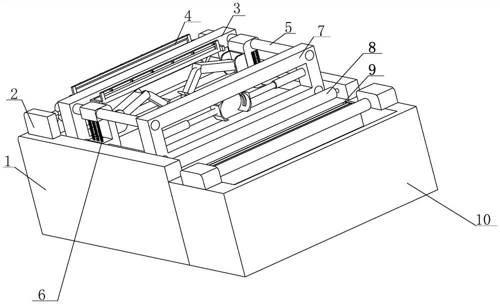
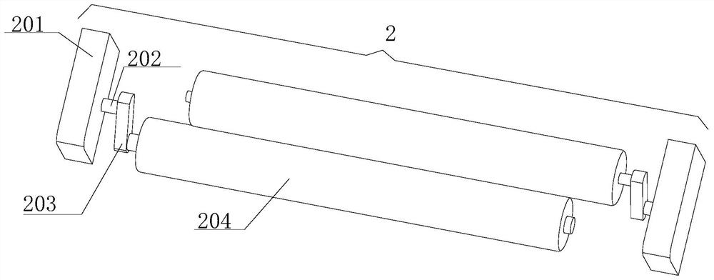
[0039] see Figure 1-3, the present invention provides a technical solution: an enameled wire hot wax automatic coating device, including a machine platform 1, an adjustment device 2 is fixedly installed on the top of the machine platform 1, and the inside of the adjustment device 2 includes a fixed platform 201, the fixed platform 201 A rotating shaft 202 is arranged inside, and one end of the rotating shaft 202 is movably connected with the inner wall of the fixed table 201, and the other end of the rotating shaft 202 is fixedly connected with an adjusting plate 203, and the end of the adjusting plate 203 away from the rotating shaft 202 is provided with an adjusting shaft, and the adjusting shaft One end of one end is movably connected with one end of the regulating plate 203, and the outer wall of the regulating shaft is movably connected with a heating roller 204.

[0040] In this embodiment, two adjustment devices 2 are arranged on the top of the machine table 1, the rot...

Embodiment 2

[0042] see Figure 1-5 As shown, on the basis of Embodiment 1, the present invention provides a technical solution: the top of the machine platform 1 is provided with a front fixed plate 3, the bottom of the front fixed plate 3 is fixedly connected with the top of the machine platform 1, and the front fixed plate 3 The outer wall of the spraying device 4 is fixedly installed with a spraying device 4. The inside of the spraying device 4 includes a connecting frame 401. The outer wall of the connecting frame 401 is fixedly connected with the outer wall of the front fixed plate 3. The inside of the connecting frame 401 is provided with a control shaft 402. The two sides of the control shaft 402 The end is movably connected with the inner wall of the connecting frame 401, and the outside of the control shaft 402 is provided with a movable rod 403. Both ends of the plate 404 are fixedly connected with the outer wall of the movable rod 403 , and the outer wall of the mounting plate ...

Embodiment 3

[0045] see Figure 1-6 As shown, on the basis of Embodiment 1 and Embodiment 2, the present invention provides a technical solution: the inside of the front fixing plate 3 is fixedly equipped with an electric screw 5, and the outer wall of the electric screw 5 is movably connected with a coating arm 6 , the inside of the coating arm 6 includes a movable concave platform 601, the outer wall of the movable concave platform 601 is fixedly equipped with a spring 602, one end of the movable concave platform 601 is fixedly installed with a movable concave platform 601, and the inner wall of the movable platform 603 is provided with a connecting arm 604 One end of connecting arm one 604 is movably connected with the inner wall of movable table 603, the other end of connecting arm one 604 is movably installed with connecting arm two 605, and the end of connecting arm two 605 away from connecting arm one 604 is fixedly connected with L-shaped frame 606, The interior of the L-shaped fra...


PUM


Abstract

The invention discloses an enameled wire hot wax automatic coating device comprising a machine table. Adjusting devices are fixedly installed at the top of the machine table, fixed tables are arranged in each adjusting device, a rotating shaft is arranged in each fixed table, and one end of each rotating shaft is movably connected with the inner wall of the corresponding fixed table. An adjusting plate is fixedly connected to the other end of each rotating shaft, an adjusting shaft is arranged at the end, away from the corresponding rotating shaft, of each adjusting plate, one end of each adjusting shaft is movably connected with one end of the corresponding adjusting plate, a heating roller is movably connected to the outer wall of each adjusting shaft, and a front fixed plate is arranged at the top of the machine table. The bottom of the front fixed plate is fixedly connected with the top of the machine table, and spraying devices are fixedly installed on the outer wall of the front fixed plate. An enameled wire can be preheated through the adjusting devices, paraffin is prevented from being rapidly solidified, the wire feeding speed of the enameled wire can be adjusted, and enameled wires with different diameters can be coated through coating arms.

Description

technical field [0001] The invention belongs to the technical field of enameled wires, in particular to an enameled wire hot wax automatic coating device. Background technique [0002] Enameled wire is a main variety of winding wire, which is composed of conductor and insulating layer. After the bare wire is annealed and softened, it is painted and baked many times. However, it is not easy to produce products that meet both standard requirements and customer requirements. It is affected by factors such as raw material quality, process parameters, production equipment, and the environment. Therefore, the quality characteristics of various enameled wires are different, but they all have Mechanical properties, chemical properties, electrical properties, thermal properties four major properties. Enameled wire is the main raw material of products such as motors, electrical appliances and household appliances. Especially in recent years, the electric power industry has achieved s...

Claims


Application Information

Patent Timeline
IPC IPC(8): B05B16/20B05B13/02B05B14/00B05B15/00B05D3/02B05D3/04
CPCB05B13/0207B05B15/00B05D3/0218B05D3/0406B05B14/00B05B16/20
Inventor 吴国军韩照虎黄万平
Owner 湖北首通电磁线科技股份有限公司
Why Eureka
Try Eureka