

Heat dissipation control system of LED lamp
A technology of LED lamps and control systems, applied in cooling/heating devices of lighting devices, lighting and heating equipment, components of lighting devices, etc., can solve problems such as power consumption, life imbalance of fans and lamps, and accelerate air circulation Effect
Inactive Publication Date: 2017-05-24
曾广文
View PDF0 Cites 0 Cited by
- Summary
- Abstract
- Description
- Claims
- Application Information
AI Technical Summary
Problems solved by technology
Therefore, in order to solve the heat dissipation problem of high-power LED lighting fixtures, some enterprises usually adopt fans to actively dissipate heat to reduce the area of the radiator and the volume of the lamps. Lifespan is seriously out of balance, and it will also cause unnecessary power consumption when the climate changes
Method used
View moreImage
Smart ImageViewing Examples

Examples
Embodiment Construction
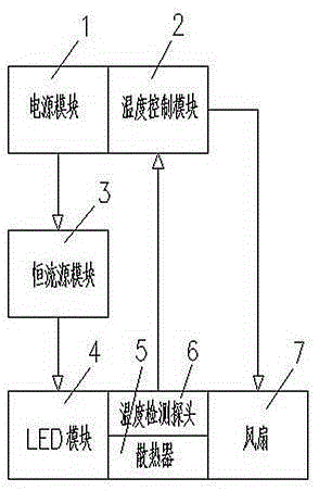
[0015] The output power of the power supply module 1 passes through the constant current source module 3 and then connects with the LED module 4. The LED module 4 is installed on the front of the radiator 5, and the fan 7 is installed on the back of the radiator 5. The power supply of the fan 7 is connected to the temperature control module 2, and the temperature control The module 2 is embedded in the power module 1 , and its temperature detection probe 6 is installed on the radiator 5 .
Login to View More PUM
 Abstract
A heat dissipation control system of an LED lamp is composed of a power supply module, a constant current source module, an LED module, a radiator, a fan and a control system of the fan. According to the heat dissipation control system of the LED lamp, a system device is formed by combining active cooling of the fan with natural convection cooling of air and through an intelligent-control heat dissipation assembly; after the lamp is energized, the fan is controlled by the temperature control module; when the temperature control module detects that the temperature of the radiator exceeds a set standard, the fan starts to work, air circulation is accelerated, and the temperature of the radiator is lowered; and when the temperature control module detects that the temperature of the radiator is lower than the set standard, the fan stops working. In this way, the service life of the fan can be greatly prolonged, and electric energy is saved.
Description
technical field [0001] The invention belongs to the technical field of LED lighting, and in particular relates to a heat dissipation control system of an LED lamp. Background technique [0002] At present, LED lighting applications are increasingly widespread, but its photoelectric conversion rate is still only about 30%, and the remaining 70% of electrical energy is still consumed in the form of heat. However, the light decay of LED is directly affected by temperature, so solving the heat dissipation problem of LED lamps is an important link in the application of LED lighting. Therefore, in order to solve the heat dissipation problem of high-power LED lighting fixtures, some enterprises usually adopt fans to actively dissipate heat to reduce the area of the radiator and the volume of the lamps. The life span is seriously out of balance, and it will also cause unnecessary power consumption when the climate changes. Contents of the invention [0003] The purpose of the ...
Claims
Login to View More Application Information
Patent Timeline
 IPC IPC(8): F21V29/503F21V29/60F21V23/00F21Y115/10
CPCF21V23/003
Inventor王磊其他发明人请求不公开姓名
Owner曾广文