Supercharge Your Innovation With Domain-Expert AI Agents!

Golf club head welding method

A golf club head and welding method technology, applied in golf balls, golf clubs, welding equipment and other directions, can solve the problems of different product quality, time-consuming and labor costs, avoid relative displacement, save labor costs, The effect of improving product qualification rate

Inactive Publication Date: 2021-05-14
FUSHENG IND CO LTD
View PDF9 Cites 0 Cited by
  • Summary
  • Abstract
  • Description
  • Claims
  • Application Information

AI Technical Summary

Problems solved by technology

However, the above-mentioned operations are all carried out manually, which consumes a lot of time and labor costs. Moreover, when welding each striking panel manually, it is impossible to accurately align each predetermined welding point each time, thus causing the product different quality

Method used


Image

  • Golf club head welding method
  • Golf club head welding method
  • Golf club head welding method

Examples


Embodiment Construction

[0037] In order to make the above-mentioned and other purposes, features and advantages of the present invention more obvious and understandable, the following is based on preferred embodiments of the present invention, and is described in detail as follows in conjunction with the accompanying drawings:

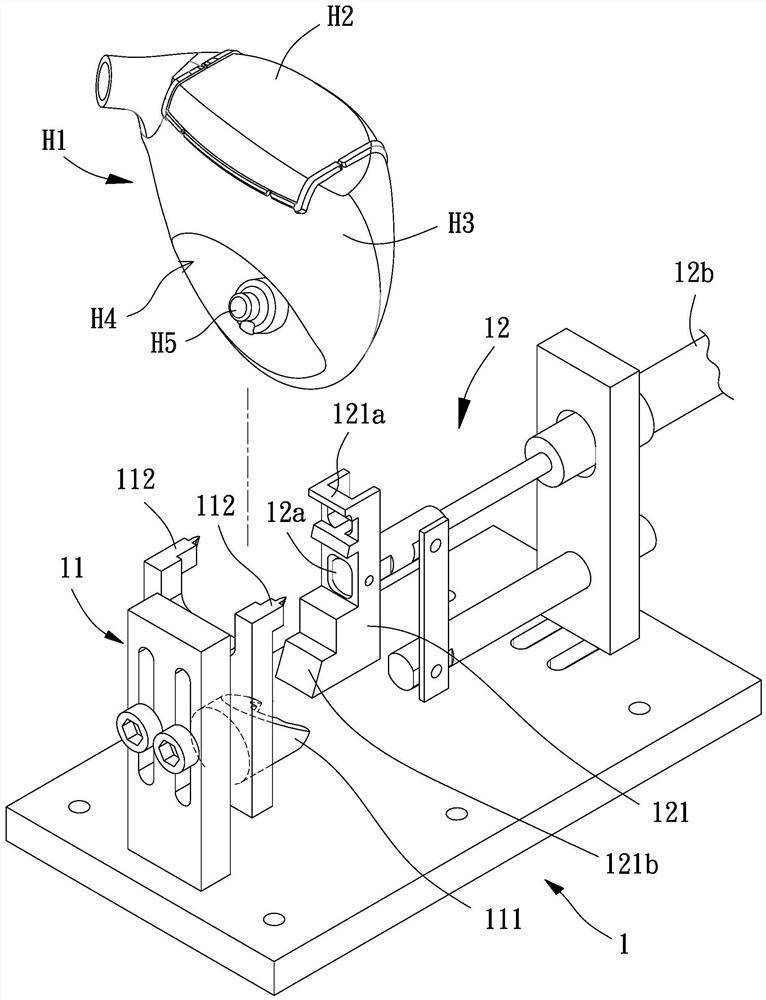
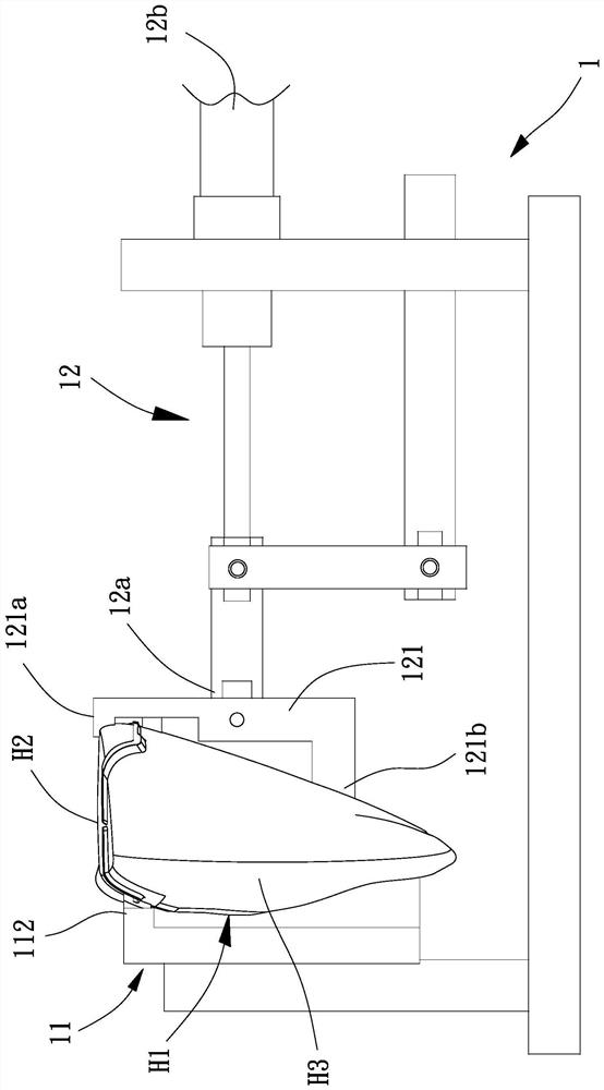
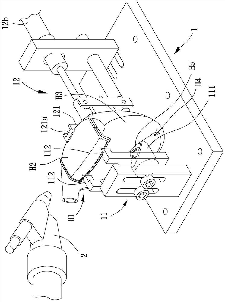
[0038] Please refer to figure 1 , 2 As shown in , 3, an embodiment of the present invention, a golf club head welding method, may include: positioning a semi-finished club head H1 with a positioning device 1, and positioning a semi-finished club head H1 with a welding part 2 Strike panel H2 for soldering.

[0039] The club head semi-finished product H1 can be matched with the striking face plate H2 in advance, and then welded after being positioned by the positioning device 1. In this embodiment, the club head semi-finished product H1 can be made of stainless steel, carbon steel, or alloy steel. , iron-manganese-aluminum or titanium alloy and other metal materials, and the ...


PUM


Abstract

The invention provides a golf club head welding method which is used for solving the problem that in the prior art, manual welding needs to consume a large amount of time and labor cost. The welding method comprises the steps of providing a positioning device, wherein the positioning device is provided with a fixing piece and an abutting piece, and the fixing piece and the abutting piece jointly position a rod head semi-finished product, so that a hitting panel of the rod head semi-finished product can be exposed; and sequentially welding multiple welding points of the hitting panel by using a welding piece.

Description

technical field [0001] The invention relates to a golf club head welding method, in particular to an automatic golf club head welding method. Background technique [0002] After the alloy is formed into a golf club head semi-finished product and a striking panel, the striking panel must be welded to the golf club head semi-finished product. Generally, when welding, the golf club head semi-finished product is first positioned manually, and then The striking panel is also positioned, and the striking panel is welded on the semi-finished golf club head, thereby completing the combination of the striking panel and the semi-finished golf club head. However, the above-mentioned operations are all carried out manually, which consumes a lot of time and labor costs. Moreover, when welding each striking panel manually, it is impossible to accurately align each predetermined welding point each time, thus causing the product The quality varies. [0003] In view of this, the existing g...

Claims


Application Information

Patent Timeline
Patent Type & Authority Applications(China)
IPC IPC(8): B23K31/02B23K37/04A63B53/04A63B102/32
CPCB23K31/02B23K37/0426A63B53/04A63B2102/32
Inventor 徐义君
Owner FUSHENG IND CO LTD
Features
  • R&D
  • Intellectual Property
  • Life Sciences
  • Materials
  • Tech Scout
  • Unparalleled Data Quality
  • Higher Quality Content
  • 60% Fewer Hallucinations
Learn More