New energy automobile charging fixing pile

A technology for new energy vehicles and fixed piles, which is applied in electric vehicle charging technology, charging stations, electric vehicles, etc., can solve problems such as increasing the hidden danger of charging piles, increasing the inner diameter of the slot, and colliding.

Inactive Publication Date: 2021-05-14
赵蓓蓓
View PDF1 Cites 1 Cited by
  • Summary
  • Abstract
  • Description
  • Claims
  • Application Information

AI Technical Summary

Problems solved by technology

[0006] Aiming at the deficiencies of the prior art, the present invention provides a new energy vehicle charging fixed pile, which solves the problem that the bottom plate of the charging pile is generally installed on the concrete ground through expansion bolts, and its inner diameter will match the outer diameter of the expansion bolts. , but when the charging pile encounters strong winds and bad weather, there will be small shaking. Multiple small shaking will cause the inner wall of the excavated slot to collide with the outer wall of the expansion bolt, resulting in an increase in the inner diameter of the slot. In turn, the expansion bolts cannot tightly limit the bottom plate of the charging pile, so that the charging pile cannot be completely fixed on the ground, which increases the safety hazard of the charging pile.

Method used


Image

  • New energy automobile charging fixing pile
  • New energy automobile charging fixing pile
  • New energy automobile charging fixing pile

Examples


Embodiment 1

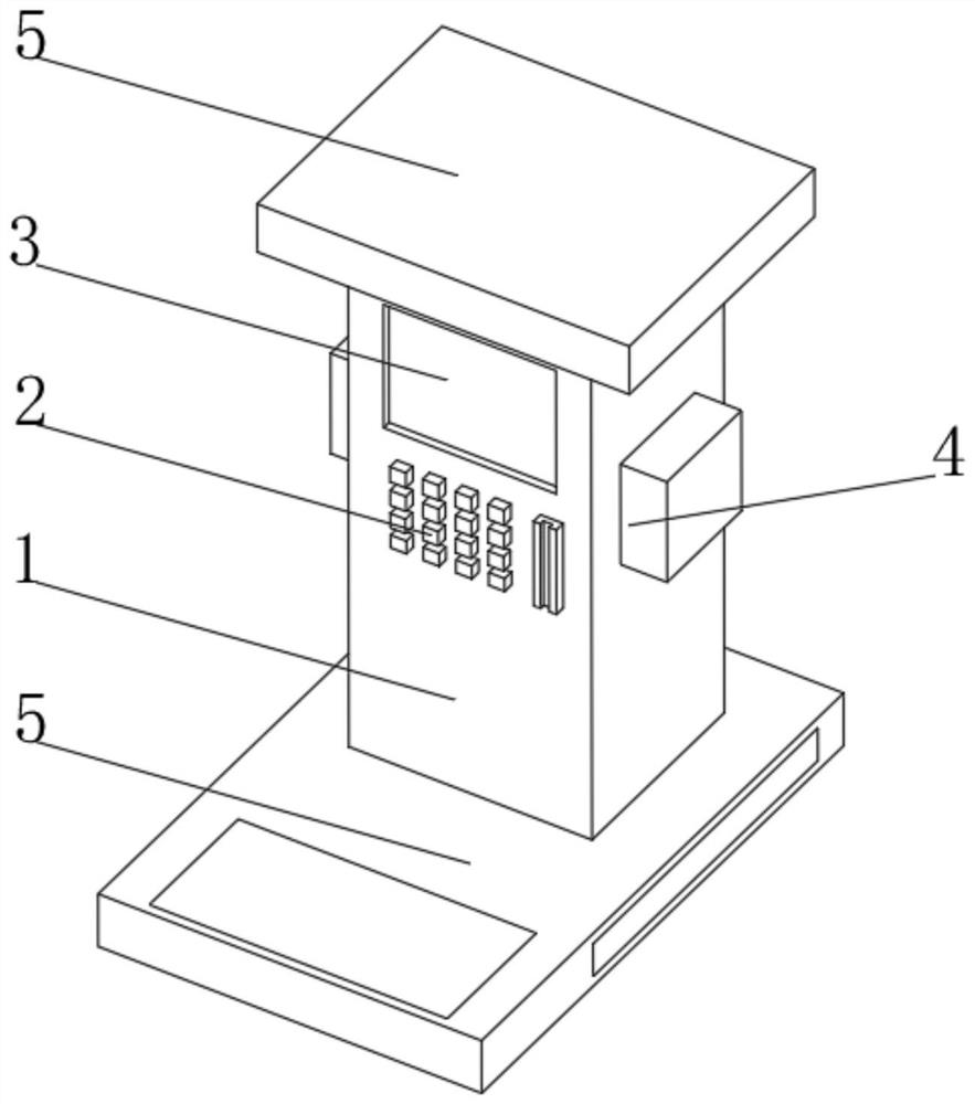
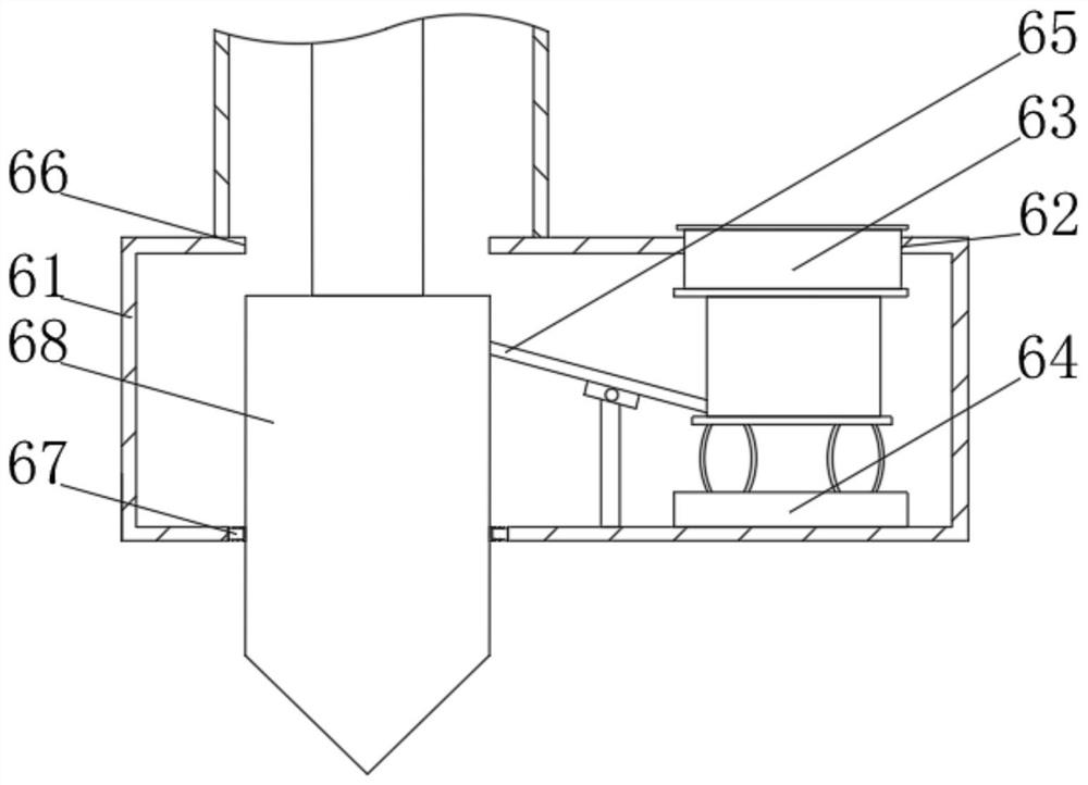
[0034]SeeFigure 1-2 The present invention provides a technical solution: a new energy vehicle charging fixing pile comprising a charging body 1, a controller 2 is provided on one side of the charging body 1, and an display 3 is provided above the controller 2, two of the charging body 1. A charging device 4 is provided on the side, and the top cover 5 is fixedly connected to the top cover 5, and the bottom portion of the charging body 1 is fixedly connected has a fixed base 6, and the fixing base 6 includes a base housing 61, a first pass groove 62, a parking plate 63 , The compression device 64, the connection lever 65, the second bucket groove 66, the elastic sealing block 67, the fixing mechanism 68, the first pass groove 62 is located at the top of the base housing 61, and the second bucket groove 66 penetrates the top of the base housing 61 and At the bottom, the inner wall side of the first pass groove 62 is slidably connected to the parking plate 63, and the bottom portion of...

Embodiment 2

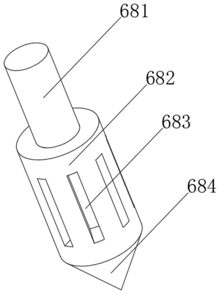
[0037]SeeFigure 3-5 The present invention provides a technical solution based on the first example: a new energy vehicle charging fixing pile, the fixing mechanism 68 includes a threaded rod 681, one end of the threaded rod 681 is provided with a drill pipe 682, and the drill pipe 682 is opened. The connecting groove 683, the drill pipe 682 is fixedly connected to one end of the threaded rod 681, and a drill bit 684 is fixed. The connecting groove 683 includes a drill rod 682 including a drill rod housing 821, and the top of the drill rod housing 821 has a third pass groove 822. The drill rod housing 821 is fixed to the inner wall side surface of the third pass groove 822, and the bobbin mechanism 823 is attached, and the drill rod housing 821 is opened, and the drill rod housing 821 is close to the inner wall of the fourth pass groove 824. The side is provided with a guide slide 825, and the inside of the guide slide 825 is rotated by the rotary sliding rod, and the drive rod 827, ...

Embodiment 3

[0040]SeeFigure 3-6The present invention provides a technical solution on the basis of the first example: a new energy vehicle charging fixing pile, the drill rod housing 821 is opened, and the drill rod housing 821 is close to the fourth channel 824. The inner wall side is provided with a guide chute 825, and the inside of the guide chute 825 is rotated by the rotary sliding rod, and the drive rod 827, the side surface of the transmission rod 827, the fourth pass groove 824 are opened, and the mounting groove 241 is opened. A telescopic airbag 242 is provided at the bottom of the inner wall, and the stretch airbag 242 is fixedly connected to one end of the mounting groove 241 is fixedly connected to the correction blade 243;

[0041]When used, the fixing rod 826 is driven through the inner wall of the guide slide 825 in the inner wall of the guide slide 825, and the fixing rod 243 is extruded by the telescopic airbag 242 inside the fourth pass groove 824, so that the correction blade ...


PUM


Abstract

The invention provides a new energy automobile charging fixing pile, a first through groove is located in the top of a base shell, a second through groove penetrates through the top and the bottom of the base shell, the side face of the inner wall of the first through groove is slidably connected with a parking plate, the bottom of the parking plate is fixedly connected with a compression device, one end, away from the parking plate, of the compression device is fixedly connected with the bottom of inner wall of base shell, the side face, close to the bottom of the base shell, of the second through groove is fixedly connected with an elastic sealing block, the side, away from the second through groove, of the elastic sealing block is slidably connected with a fixing mechanism, one side of the fixing mechanism is connected with the compression device through a connecting lever, and one side of the connecting lever is fixedly connected with the bottom of the inner wall through a rotating seat and a fixing rod. The invention relates to the technical field of new energy automobile charging. According to the new energy automobile charging fixing pile, the situation that a drill rod shakes in a drill hole, so that the hole diameter of the drill hole is increased is avoided, and therefore the situation that personnel and property losses are caused and the working cost is increased due to dangers caused by the fact that the device cannot be firmly connected with the ground is avoided.

Description

Technical field[0001]The present invention relates to the field of new energy vehicle charging technology, and is specifically a new energy vehicle charging fixing pile.Background technique[0002]The new energy vehicle is a manner to provide a traditional vehicle to provide power to the vehicle, and the equipment given the new energy vehicle charging is a charging pile, a charging pile connection, a distribution box near the vicinity of the charging box, by converting the electricity conversion of the distribution box After delivery, transport it to the new energy car, and the low-carbon emissions from the air environment will be purchased and the low-carbon emissions from new energy vehicles have become my country's support.[0003]For example, China Patent CN111516531A discloses a new energy vehicle charging pile fixing device, which is installed in the electric pile installation box, and is stored in the electric pile installation box, Piles of electric pile devices form protection;...

Claims


Application Information

Patent Timeline
IPC IPC(8): B60L53/31B60L53/30
CPCB60L53/30B60L53/31Y02T10/70Y02T10/7072Y02T90/12
Inventor 刘轩彤
Owner 赵蓓蓓
Why Eureka
Try Eureka