Air injection structure of air layer resistance reduction device, ship air layer resistance reduction system and air layer resistance reduction ship

A drag reduction device and gas layer technology, applied in the direction of ship hull, hull design, ship construction, etc., can solve the problems affecting the overall strength of the ship, and achieve the effect of saving workload, reducing costs, and facilitating opening

Pending Publication Date: 2021-05-14
CSIC SHANGHAI MARINE ENERGY SAVING TECH DEV CO LTD
View PDF0 Cites 0 Cited by
  • Summary
  • Abstract
  • Description
  • Claims
  • Application Information

AI Technical Summary

Problems solved by technology

[0005] The object of the present invention is to provide the jet structure of the air layer drag reduction device, the air layer drag reduction system of the ship and the air layer drag reduction ship, so as to solve the problem in the prior art that the pressure stabilizing chamber penetrates through the longitudinal and affects the overall strength of the ship

Method used


Image

  • Air injection structure of air layer resistance reduction device, ship air layer resistance reduction system and air layer resistance reduction ship
  • Air injection structure of air layer resistance reduction device, ship air layer resistance reduction system and air layer resistance reduction ship
  • Air injection structure of air layer resistance reduction device, ship air layer resistance reduction system and air layer resistance reduction ship

Examples


Embodiment 1

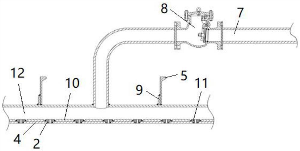
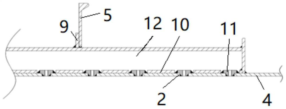
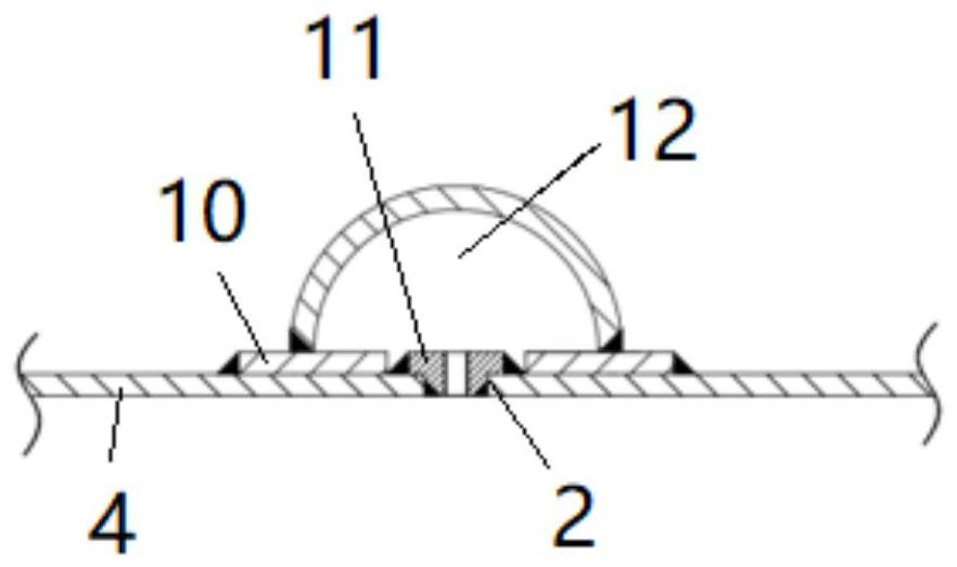
[0035] see Figure 4 to Figure 6 , the present embodiment provides an air injection structure of an air layer drag reduction device, comprising a pressure stabilizing tube 1 and a number of spray holes 2 arranged on the bottom plate 4 of the ship, the stabilizing tube 1 is arranged above the longitudinal 5, and the pressure stabilizing tube 1 The inner chamber is a pressure-stabilizing chamber 12, and the pressure-stabilizing pipe 1 is provided with a number of air delivery pipes 3 corresponding to the nozzle holes 2 one by one.

[0036] In the prior art, the plenum chamber 12 is directly connected with the ship bottom plate 4 (see attached Figures 1 to 3 ), so it will run through the longitudinal bone 5, in order to compensate for the influence of opening holes on the longitudinal bone 5 on the overall strength of the ship, it is necessary to add a longitudinal bone patch 9 to the longitudinal bone 5. However, in this embodiment, the pressure stabilizing chamber 12 is arrang...

Embodiment 2

[0051] This embodiment provides an air layer drag reduction system for a ship, including the air jet structure of the air layer drag reduction device as described in Embodiment 1. Since the air jet structure of the air layer drag reduction device has little influence on the structural strength of the hull, there is no need to cut the longitudinal bone 5. Installation of components such as the longitudinal bone patch 9, the plenum backing plate 10, and the nozzle 11 saves costs, reduces installation procedures and time, and thus enhances the competitiveness of the ship air layer drag reduction system provided by this embodiment.


PUM


Abstract

The invention discloses an air injection structure of an air layer resistance reduction device, a ship air layer resistance reduction system and an air layer resistance reduction ship. The air injection structure of the air layer resistance reduction device comprises a pressure stabilizing cavity and a plurality of spray holes formed in a ship bottom plate, a pressure stabilizing pipe is arranged above a longitudinal bone, an inner cavity of the pressure stabilizing pipe is the pressure stabilizing cavity, the pressure stabilizing pipe is provided with a plurality of air conveying pipes in one-to-one correspondence with the spray holes, and the two ends of each air conveying pipe communicate with the pressure stabilizing pipe and the corresponding spray hole correspondingly. In the prior art, the pressure stabilizing cavity is directly connected with the ship bottom plate, so that the pressure stabilizing cavity can penetrate through the longitudinal bone, and a longitudinal bone reinforcing plate needs to be additionally arranged on the longitudinal bone in order to compensate for the influence of opening holes in the longitudinal bone on the overall strength of the ship. According to the embodiment, the pressure stabilizing cavity is formed above the longitudinal bone, the longitudinal bone does not need to be cut or penetrate through, and the structural strength of the ship cannot be affected.

Description

technical field [0001] The invention belongs to the field of air layer drag reduction ships, and in particular relates to an air layer drag reduction device jet structure, a ship air layer drag reduction system and an air layer drag reduction ship. Background technique [0002] Marine air layer drag reduction technology, through a specially designed device, ventilates to the bottom of the ship, forms and maintains a layer of air layer on the bottom of the ship, isolates the bottom surface of the ship from water, reduces the wet surface area, and can significantly reduce ship resistance and fuel consumption . This technology is different from other relatively mature energy-saving devices, such as vortex-eliminating fins, energy-saving ducts, etc., in terms of mechanism and location, so it can be used in conjunction with other energy-saving devices. It is a new energy-saving and emission-reducing technology for ships with great potential. [0003] In the process of market pro...

Claims


Application Information

Patent Timeline
Patent Type & Authority Applications(China)
IPC IPC(8): B63B1/38
CPCB63B1/38Y02T70/10
Inventor 陈少峰高丽瑾恽秋琴严周广陈雷强黄国富夏灏超吴赞
Owner CSIC SHANGHAI MARINE ENERGY SAVING TECH DEV CO LTD
Why Eureka
Try Eureka