
Magnetic switch installation structure for controlling stroke of large-diameter cylinder

A magnetic switch and installation structure technology, applied in the direction of fluid pressure actuation device, etc., can solve the problems affecting the precision of piston rod movement, affecting the control precision of mechanical equipment, and the processing precision of cylinder piston rod and cylinder body is difficult to guarantee, etc., to achieve the improvement The effect of movement accuracy

Pending Publication Date: 2021-05-14
DATANG GUIZHOU FAER POWER GENERATION
View PDF0 Cites 1 Cited by
  • Summary
  • Abstract
  • Description
  • Claims
  • Application Information

AI Technical Summary

Problems solved by technology

[0003] The existing cylinder products have been standardized and serialized, and people only need to choose the corresponding model when using them. However, for some cylinders with large bore and large stroke, since the cylinder is driven by air power to move the piston rod back and forth , when the bore size or stroke size increases, the machining accuracy of the cylinder piston rod and the cylinder body is not easy to guarantee. Usually, the assembly gap between the cylinder piston rod and the cylinder body also increases, causing the piston rod to move back and forth When moving, it is easy to swing along the radial direction of the piston rod, which affects the accuracy of the reciprocating motion of the piston rod, especially at both ends of the reciprocating stroke of the cylinder, the radial vibration is particularly obvious, which affects the accuracy of the cylinder as a power actuator. It also affects the corresponding control accuracy of the entire mechanical equipment

Method used


Image

  • Magnetic switch installation structure for controlling stroke of large-diameter cylinder
  • Magnetic switch installation structure for controlling stroke of large-diameter cylinder
  • Magnetic switch installation structure for controlling stroke of large-diameter cylinder

Examples


Embodiment Construction

[0018] The technical solution of the present invention is further described below, but the scope of protection is not limited to the description.

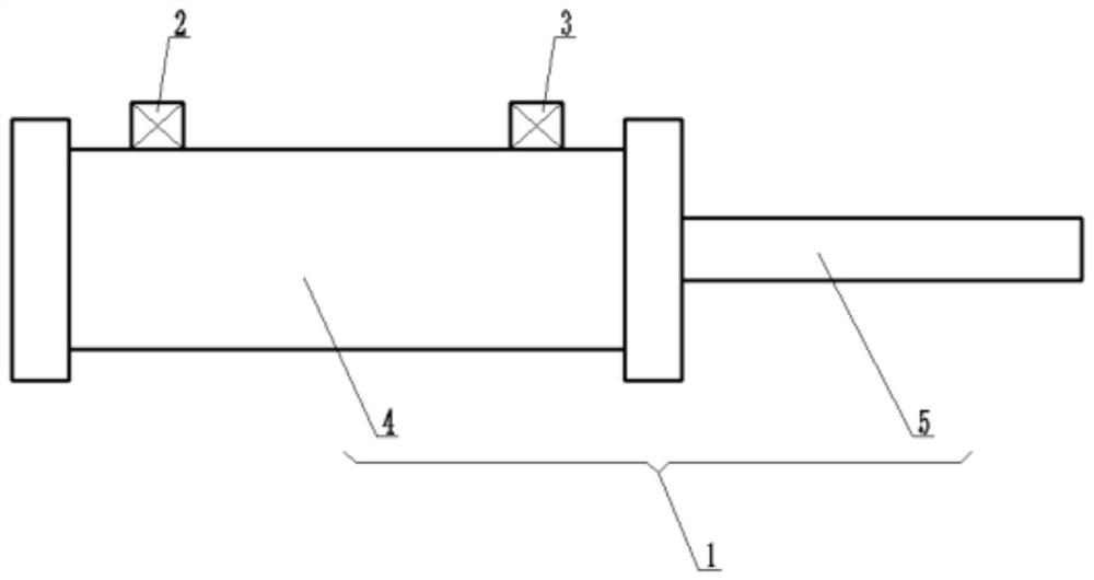
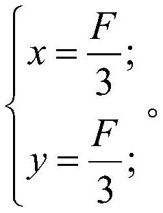
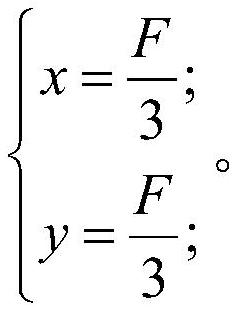
[0019] like figure 1 As shown, the present invention provides a building material performance testing system, including a cylinder 1, a magnetic switch A2 and a magnetic switch B3, the cylinder 1 includes a cylinder 4 and a piston rod 5 that can reciprocate along the length of the cylinder 4, and the magnetic switch A2 and the magnetic switch B3 are fixedly installed on the outer surface of the cylinder 4, assuming that the stroke of the cylinder 1 is F, the distance between the installation position of the magnetic switch A2 and the bottom of the cylinder 4 is x, and the installation position of the magnetic switch B3 is relative to the top of the cylinder 4 The distance is y, then F, x, y satisfy the following relationship:

[0020]

[0021] Further, it is preferable that the magnetic switch A2 is a magnetic switch with an au...


PUM


Abstract

The invention provides a magnetic switch installation structure for controlling the stroke of a large-diameter cylinder. The magnetic switch installation structure comprises the cylinder, a magnetic switch A and a magnetic switch B. The cylinder comprises a cylinder body and a piston rod capable of reciprocating along the length direction of the cylinder body, the magnetic switch A and the magnetic switch B are both fixedly installed on the outer surface of the cylinder body, and the stroke of the cylinder is set as F. The distance between the installation position of the magnetic switch A and the bottom end of the cylinder body and the distance between the installation position of the magnetic switch B and the top end of the cylinder body are each one third of the stroke of the cylinder. Due to the adoption of the technical scheme, the actual effective stroke of reciprocating motion of the cylinder can be smaller than the rated nominal stroke and located in the middle of the range of the rated nominal stroke, and the influence of radial swing generated when the cylinder moves at the two ends of the rated nominal stroke on motion precision and corresponding control precision can be avoided; and the action accuracy of a power actuating mechanism and the control precision of the whole mechanical equipment can be conveniently improved.

Description

technical field [0001] The invention belongs to the technical field of pneumatic equipment, and in particular relates to a magnetic switch installation structure for controlling the stroke of a cylinder with a large bore diameter. Background technique [0002] Cylinders are widely used in various mechanical equipment. In these mechanical equipment, cylinders are used as reciprocating power actuators. In order to control the movement stroke of the cylinders, it is usually necessary to install corresponding magnetic switches on the cylinders. The magnetic switch cylinders are used to detect The position of the cylinder stroke can replace the machine-controlled valve or stroke switch, and there is no need to set a bumper at the end of the piston rod, so it is easy to use and compact in structure. High reliability, long life, low cost, fast switching response time, so it is widely used. [0003] The existing cylinder products have been standardized and serialized, and people on...

Claims


Application Information

Patent Timeline
Patent Type & Authority Applications(China)
IPC IPC(8): F15B15/14F15B15/20F15B15/24F15B15/28
CPCF15B15/1423F15B15/20F15B15/24F15B15/2807
Inventor 姜波王仲杨礼武铁
Owner DATANG GUIZHOU FAER POWER GENERATION
Learn More