
Overturning mechanism for bearing seat machining

A technology of overturning mechanism and bearing seat, which is applied in the direction of bearings, bearing components, shafts and bearings, etc., which can solve the problems of long time-consuming manual overturning, poor efficiency, and safety damage to operators

Active Publication Date: 2021-05-14
山东百昌汽车零部件有限公司
View PDF17 Cites 0 Cited by
  • Summary
  • Abstract
  • Description
  • Claims
  • Application Information

AI Technical Summary

Problems solved by technology

[0002] Bearing is an important part in machinery production. It is generally used to connect relatively rotating workpieces to reduce the friction between workpieces during rotation, thereby prolonging the service life of the equipment and facilitating operation and use. In processing and production Bearings generally need to use bearing processing equipment. This type of equipment is usually composed of a pressure device and a base. The bearing is processed by pressure. When processing the bearing, in order to ensure the accuracy of the bearing, it is necessary to process the upper and lower sides of the bearing, so The bearing needs to be turned over during processing, but when turning over manually, the press may cause safety damage to the operator, and the manual turning takes a long time, affecting work efficiency
[0003] Aiming at the deficiencies of the prior art, the present invention provides a processing turning mechanism for bearing seats, which has the advantage of automatic turning and solves the problem of low safety and poor efficiency of manual turning

Method used

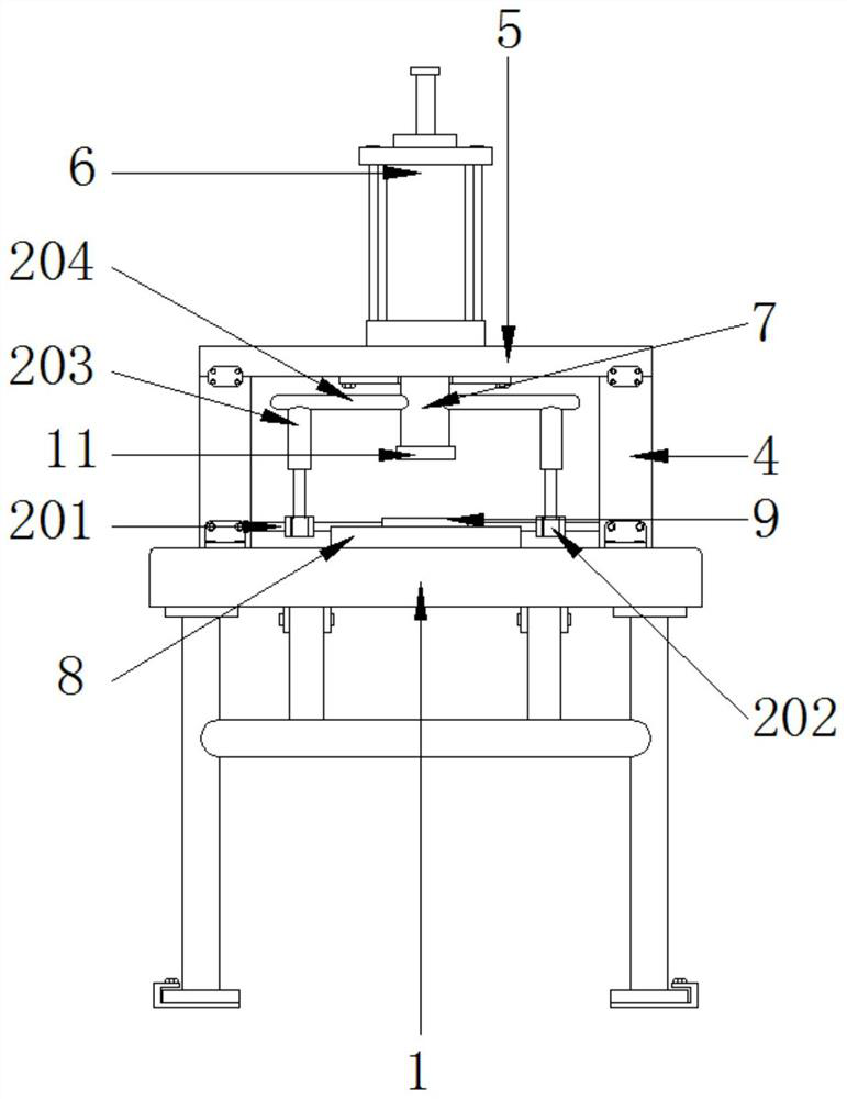
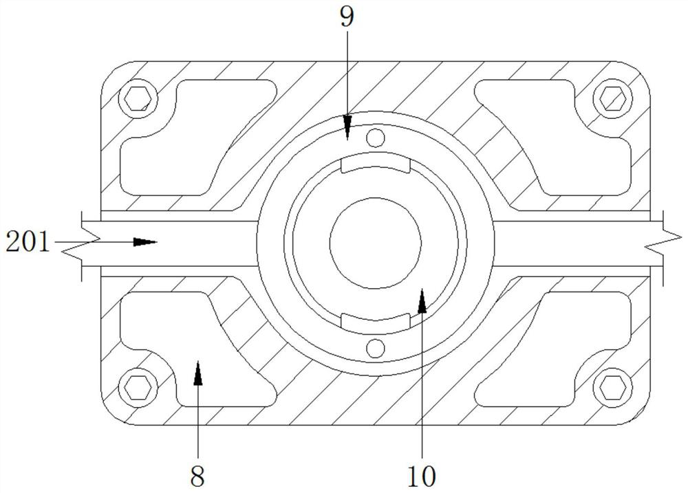
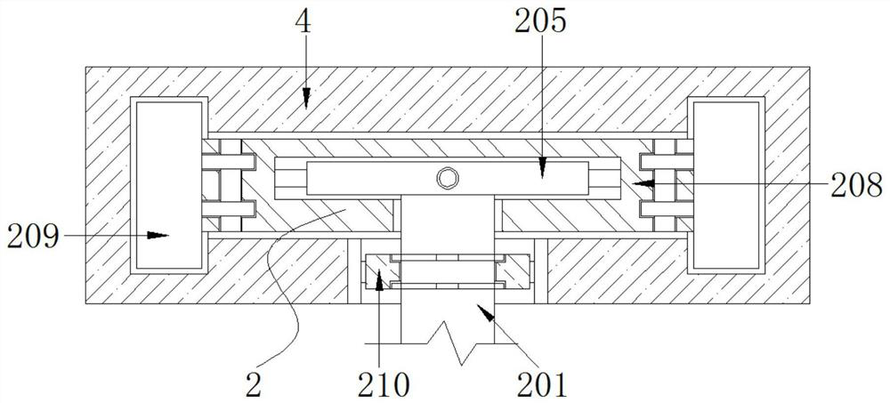

Image

  • Overturning mechanism for bearing seat machining
  • Overturning mechanism for bearing seat machining
  • Overturning mechanism for bearing seat machining

Examples


Embodiment Construction

[0021] The following will clearly and completely describe the technical solutions in the embodiments of the present invention with reference to the accompanying drawings in the embodiments of the present invention. Obviously, the described embodiments are only some, not all, embodiments of the present invention. Based on the embodiments of the present invention, all other embodiments obtained by persons of ordinary skill in the art without making creative efforts belong to the protection scope of the present invention.

[0022] see Figure 1-2 , a bearing seat processing turning mechanism, including a base 1, a turning device 2 and a clamping device 3, a side plate 4 is fixedly installed on the top of the base 1, a support frame 5 is fixedly installed on the top end of the side plate 4, and a pressing frame is fixedly installed on the top end of the support frame 5 Pump 6, the bottom end of the pump 6 is movable with a pressure rod 7, the bottom end of the pressure rod 7 is fi...


PUM


Abstract

The invention relates to the technical field of bearings, and discloses an overturning mechanism for bearing seat machining. The overturning mechanism for bearing seat machining comprises a base, an overturning device and a clamping device, wherein a side plate is fixedly installed at the top end of the base, a supporting frame is fixedly installed at the top end of the side plate, a pressing pump is fixedly installed at the top end of the supporting frame, a pressing rod is movably installed at the bottom end of the pressing pump, a pressing plate is fixedly installed at the bottom end of the pressing rod, a fixing seat is fixedly installed at the top end of the base, a fixing ring is movably installed in the fixing seat, and a bearing is movably installed in the fixing ring; the overturning device is movably installed on the inner side of the side plate; and the clamping device is movably installed in the fixing ring. According to the overturning mechanism for bearing seat machining, the purpose of overturning a machined workpiece can be achieved through the reciprocating performance of machining of the device, the manual overturning procedure is omitted, and the possibility that an operator is in danger during manual operation is avoided.

Description

technical field [0001] The invention relates to the technical field of bearings, in particular to a machining turning mechanism for a bearing seat. Background technique [0002] Bearing is an important part in machinery production. It is generally used to connect relatively rotating workpieces to reduce the friction between workpieces during rotation, thereby prolonging the service life of the equipment and facilitating operation and use. In processing and production Bearings generally need to use bearing processing equipment. This type of equipment is usually composed of a pressure device and a base. The bearing is processed by pressure. When processing the bearing, in order to ensure the accuracy of the bearing, it is necessary to process the upper and lower sides of the bearing, so The bearing needs to be turned over during processing, but when turning over manually, the press may cause safety damage to the operator, and the manual turning takes a long time, which affects...

Claims


Application Information

Patent Timeline
IPC IPC(8): F16C33/00B30B15/00
CPCF16C33/00B30B15/0023B30B15/0052F16C2220/40
Inventor 汪红娅
Owner 山东百昌汽车零部件有限公司
Learn More