
Tool setting method, system and device

A technology of tool tip and tool point, applied in the field of systems, devices, and tool setting methods, can solve the problems of dangerous occurrence and high level of operators, achieve the possibility of avoiding danger, and solve the effect of high skill level

Inactive Publication Date: 2018-11-13
GUANGDONG UNIV OF TECH
View PDF8 Cites 5 Cited by
  • Summary
  • Abstract
  • Description
  • Claims
  • Application Information

AI Technical Summary

Problems solved by technology

[0005] The purpose of the present invention is to provide a tool setting method, which can solve the problem of requiring a high level of skill of the operator, and secondly, avoid the possibility of the operator being in danger near the lathe

Method used


Image

  • Tool setting method, system and device
  • Tool setting method, system and device
  • Tool setting method, system and device

Examples


Embodiment Construction

[0027] The following will clearly and completely describe the technical solutions in the embodiments of the present invention with reference to the accompanying drawings in the embodiments of the present invention. Obviously, the described embodiments are only some, not all, embodiments of the present invention. Based on the embodiments of the present invention, all other embodiments obtained by persons of ordinary skill in the art without making creative efforts belong to the protection scope of the present invention.

[0028] In order to enable those skilled in the art to better understand the solution of the present invention, the present invention will be further described in detail below in conjunction with the accompanying drawings and specific embodiments.

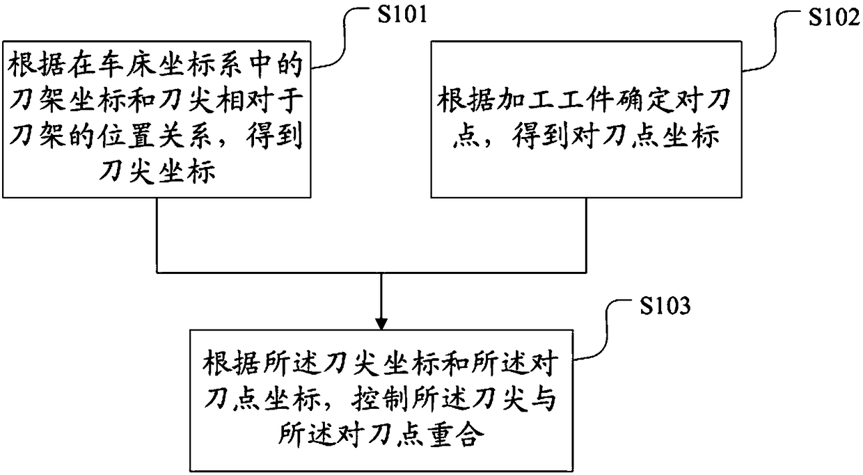
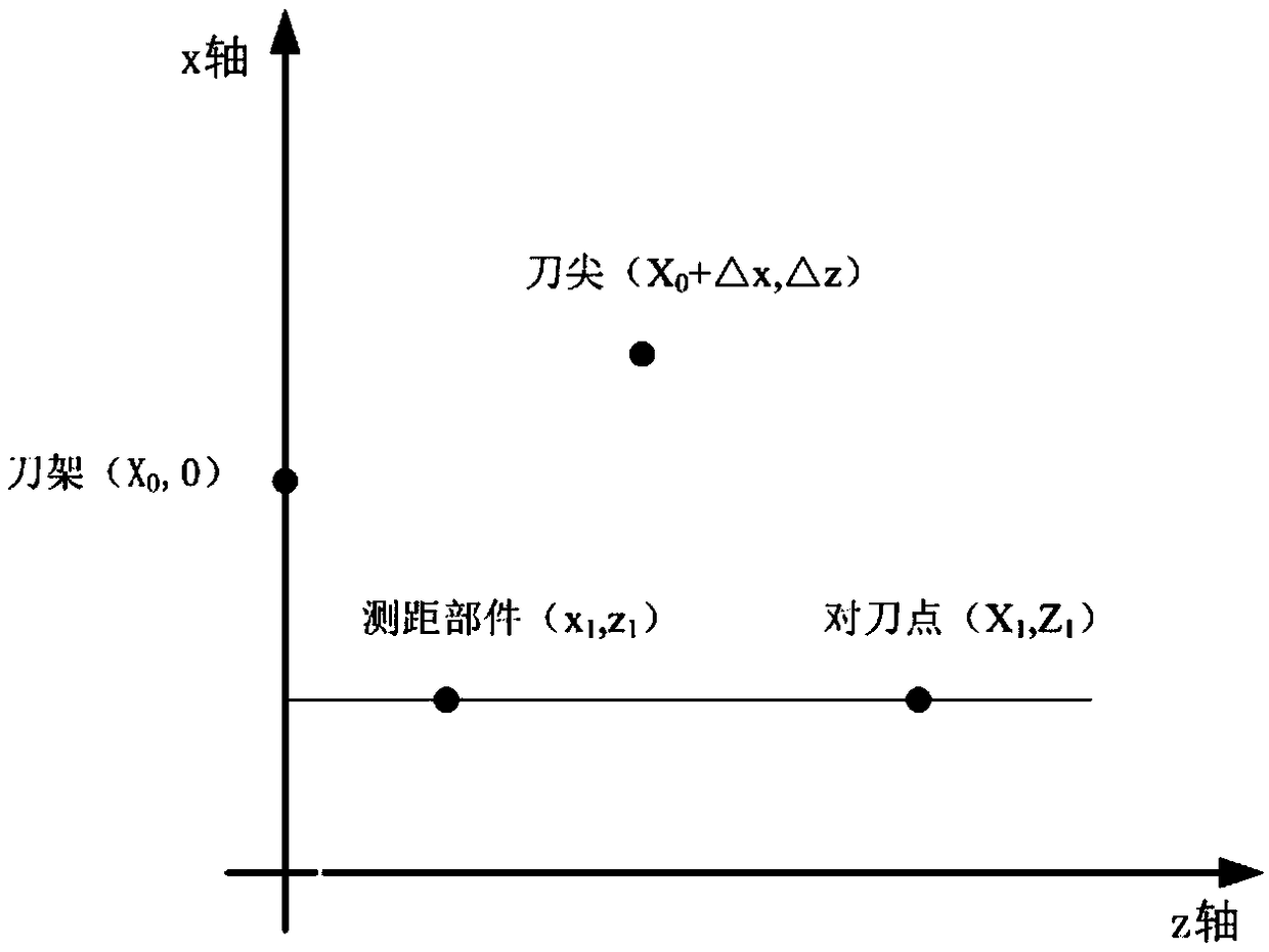
[0029] Please refer to figure 1 and figure 2 , figure 1 The flow chart of the tool setting method provided by the present invention, figure 2 for figure 1 The schematic diagram of the coordinates of each compo...


PUM


Abstract

The invention discloses a tool setting method which comprises the following steps: according to a tool rest coordinate in a lathe coordinate system as well as the relative position relation between atool nose and a tool rest, acquiring a tool nose coordinate; determining a tool setting point according a to-be-processed workpiece, and acquiring a tool setting point coordinate; and according to thetool nose coordinate and the tool setting point coordinate, controlling the tool nose to overlap the tool setting point. By adoption of the above tool setting method, the tool setting process can beautomatically controlled; the problem that an operator at a relatively high level of skill is needed can be solved; and besides, the possibility that the operator is confronted with danger near a lathe can be avoided. The invention further discloses a tool setting system and a tool setting device which correspond to the above tool setting method.

Description

technical field [0001] The invention relates to the field of mechanical manufacturing, in particular to a tool setting method, system and device. Background technique [0002] A lathe is a mechanical processing device that mainly uses a turning tool to turn a workpiece that is clamped on a spindle and rotates at a high speed. Before turning the workpiece, tool setting must be carried out. The purpose of tool setting is to determine the position of the origin of the workpiece coordinate system (that is, the tool setting point) in the lathe coordinate system to ensure the accuracy of subsequent turning processes. [0003] At present, the tool setting usually uses a contact tool setting instrument for tool setting. During the tool setting process, the operator needs to use the hand wheel to control the movement of the tool holder, so that the tip of the tool gradually approaches the end face of the workpiece, and the cutting surface is cut at the end surface of the workpiece. ...

Claims


Application Information

Patent Timeline
IPC IPC(8): B23B25/06
CPCB23B25/06
Inventor 尹自强孔德坤游杰魏棵榕张霞峰
Owner GUANGDONG UNIV OF TECH
Learn More