Floor heating water distributing and collecting device and flushing method thereof

A sub-collector and floor heating technology, which is applied in the field of sub-collectors for floor heating and its flushing, can solve the problems of high purchase cost of pressure detection devices, reduced heating effect, and blocked pipe network, etc., to solve the problem of declining heating efficiency and reducing economic costs. The effect of burdening and reducing the cost of employment

Pending Publication Date: 2021-05-14
海纳云物联科技有限公司
View PDF8 Cites 1 Cited by
  • Summary
  • Abstract
  • Description
  • Claims
  • Application Information

AI Technical Summary

Problems solved by technology

Due to the long laying of floor heating pipelines, the additives used in the maintenance of pipelines in the water supply of heating companies, and the aging problem of the main network, there are more impurities in the water supply pipe network, and the flow rate of the floor heating branch pipe loop is relatively slow, resulting in easy deposition in the pipe network Impurities block the pipe network, resulting in a decline in the heating effect and causing a bad experience for users. When the floor heating pipe is blocked, professional maintenance personnel are often required to go to the site to deal with it. It is difficult to deal with it in a timely manner due to the need to take into account the owner's time. Manual processing needs to be charged, which also causes a certain economic burden on the owner
In view of the above problems, the invention patent with the Chinese patent number 201710408093.5 proposes a cleaning method and device for the floor heating system. It mainly uses the method of detecting the pressure difference of each pipeline to judge whether the floor heating pipeline is blocked. Detect the pressure value of the water pipe, so it needs to use multiple pressure detection devices, and the purchase cost of the pressure detection device is very high, so this patent has the problem of relatively high installation and use costs in practical applications

Method used


Image

  • Floor heating water distributing and collecting device and flushing method thereof
  • Floor heating water distributing and collecting device and flushing method thereof

Examples


Embodiment 2

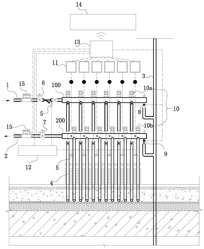
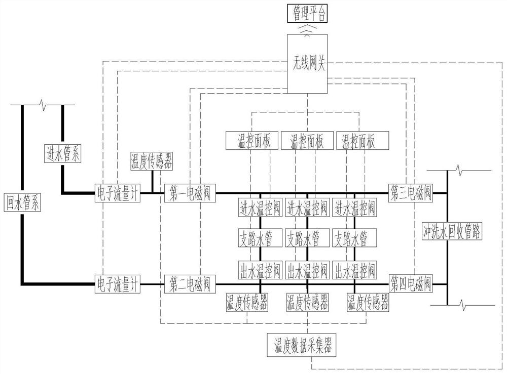
[0057] A method for flushing a floor heating sub-collector, comprising the following steps:

[0058] Step 1. Obtain the temperature data of the water inlet pipe system 1 and each branch water pipe 4 in real time, as well as the indoor temperature data of the space where each branch water pipe 4 is located;

[0059] Step 2. Calculate the temperature difference between the water inlet pipe system 1 and each branch water pipe 4, and judge whether the temperature difference is greater than the preset temperature difference. If the temperature difference is greater than the preset temperature difference, execute the next step; otherwise, do not execute;

[0060] Step 3, extract the indoor temperature data of the space where the branch water pipe 4 is located with a temperature difference value greater than the preset temperature difference value, and judge whether the indoor temperature is lower than the preset temperature value, if it is smaller, execute the next step, otherwise do...


PUM


Abstract

The invention relates to a floor heating water distributing and collecting device which comprises a water inlet pipe system, a water return pipe system, a flushing water recycling pipeline, a plurality of branch water pipes, temperature sensors installed on the water inlet pipe system and the branch water pipes, a first electromagnetic valve installed on the water inlet pipe system, a second electromagnetic valve installed on the water return pipe system, a third electromagnetic valve arranged between the water inlet pipe system and the flushing water recycling pipeline, a fourth electromagnetic valve arranged between the water return pipe system and the flushing water recycling pipeline, at least one temperature control valve installed on each branch water pipe, and a control system electrically connected with temperature control valves, the temperature sensors, the first electromagnetic valve, the second electromagnetic valve, the third electromagnetic valve and the fourth electromagnetic valve; and the control system can control the temperature control valves and the electromagnetic valves to act and is used for flushing the branch water pipes. The invention further relates to a flushing method of the floor heating water distributing and collecting device, so that automatic flushing can be achieved, and the problem that the branch water pipes are prone to being blocked is solved.

Description

technical field [0001] The invention relates to floor heating equipment, in particular to a floor heating sub-collector and a washing method thereof. Background technique [0002] Floor heating equipment is very common in some high-end commercial buildings due to its good heat dissipation effect and the fact that it does not affect the indoor appearance after installation. Due to the long laying pipeline of floor heating, additives used for maintenance of pipelines in the water supply of the heating company, and the aging problem of the main network, there are more impurities in the water supply pipe network, and the flow rate of the floor heating branch pipe loop is relatively slow, resulting in easy deposition in the pipe network Impurities block the pipe network, resulting in a decline in the heating effect and causing a bad experience for users. When the floor heating pipe is blocked, professional maintenance personnel are often required to go to the site to deal with it...

Claims


Application Information

Patent Timeline
Patent Type & Authority Applications(China)
IPC IPC(8): F24D3/10F28G9/00F28G15/00
CPCF24D3/1066F28G9/00F28G15/003
Inventor 陈斌吕昌昌贺嵩李剑波孙圣伟王成龙柳敏
Owner 海纳云物联科技有限公司
Why Eureka
Try Eureka