Air outlet structure of air conditioning equipment

A technology of air-conditioning equipment and air outlet cavity, which is applied in the field of air outlet structure of air-conditioning equipment, can solve the problems of single function of the air outlet structure, lack of intelligence, poor use effect, etc., achieve high degree of intelligence, good use effect, effective Useful effect

Inactive Publication Date: 2021-05-14
台州来智科技有限公司
View PDF8 Cites 0 Cited by
  • Summary
  • Abstract
  • Description
  • Claims
  • Application Information

AI Technical Summary

Problems solved by technology

[0002] The air conditioner is an air conditioner, which is a unit used to provide a space area to deal with changes in air temperature. Its function is to adjust the temperature and air flow rate of the air in the room to meet the requirements of human comfort or process. ; With the gradual improvement of people's quality of life, air-conditioning equipment has become an indispensable daily necessities in people's daily life. Afterwards, it will affect the air in the house and make the air in the house extremely dry. Because the air in the house becomes extremely dry, the user's experience effect is greatly reduced, and it is inconvenient to purify the indoor air, and the use effect is not good. It is also inconvenient to automatically adjust the indoor air humidity, not intelligent enough, and it is inconvenient to disassemble and assemble the deflector, which will have a negative impact on the cleaning and cleaning of the deflector, which needs to be improved

Method used


Image

  • Air outlet structure of air conditioning equipment
  • Air outlet structure of air conditioning equipment
  • Air outlet structure of air conditioning equipment

Examples


Embodiment Construction

[0038] In order to make the object, technical solution and advantages of the present invention clearer, the present invention will be further described in detail below in combination with specific embodiments and with reference to the accompanying drawings. It should be understood that these descriptions are exemplary only, and are not intended to limit the scope of the present invention. Also, in the following description, descriptions of well-known structures and techniques are omitted to avoid unnecessarily obscuring the concept of the present invention.

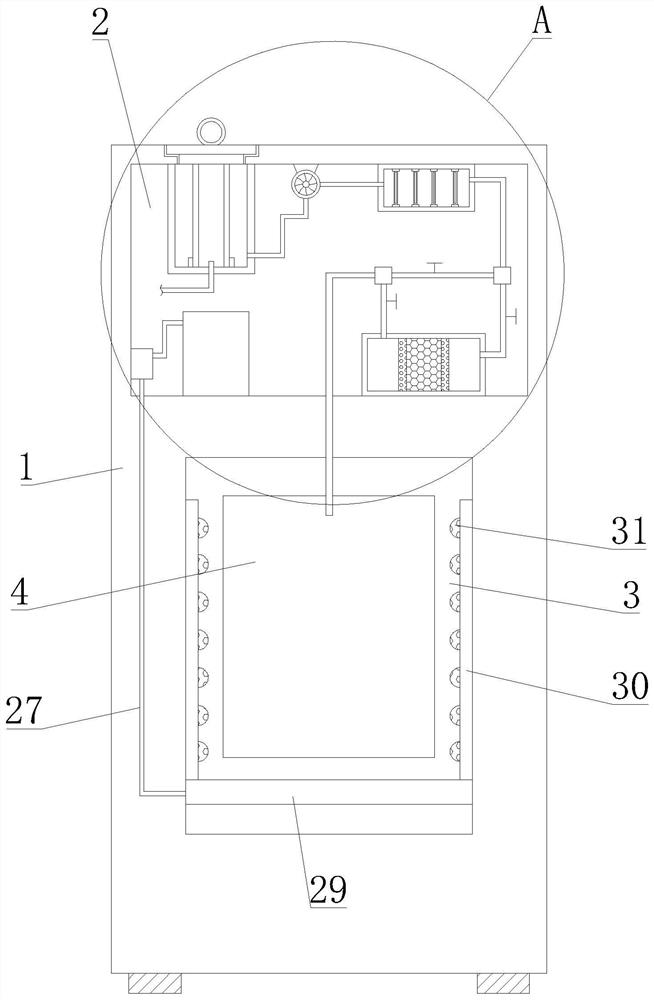
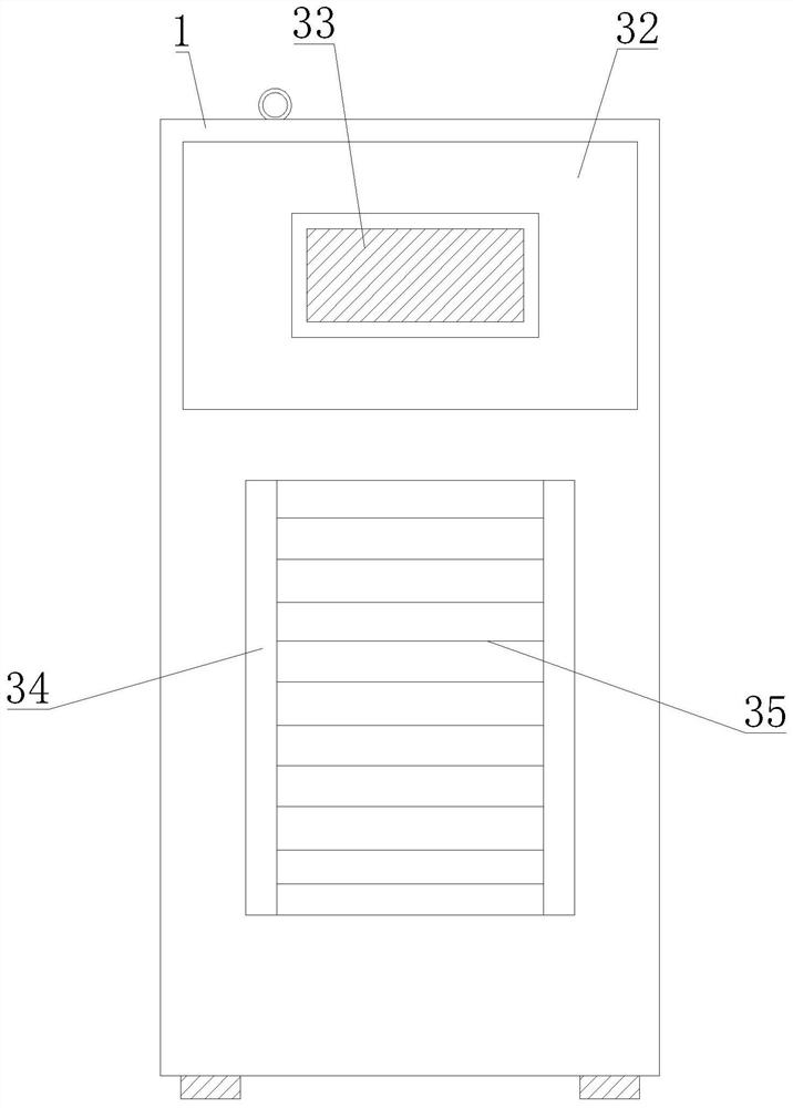
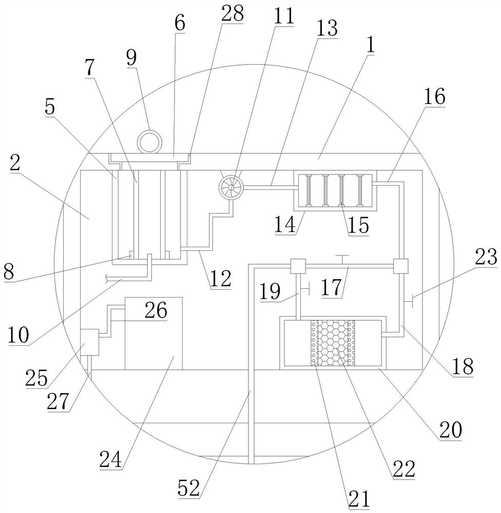
[0039] Such as Figure 1-7 As shown, an air outlet structure of an air conditioner proposed by the present invention includes an air conditioner body 1, a seal 6, a purification device 7, an air inlet pipe 10, a first connection box 14, a second connection box 20, a humidifier 24, Blower 25, connector 34, air distribution plate 36, spring 41, central processing unit 47 and exhaust pipe 52;

[0040] The air-conditioning eq...


PUM


Abstract

An air outlet structure of air conditioning equipment comprises an air conditioning equipment body; a placing chamber is arranged in the air conditioning equipment body, and a fixed cylinder is arranged in the placing chamber; the bottom of a purification device presses the inner bottom end of the fixed cylinder; a first connecting pipe and a second connecting pipe are arranged on an exhaust fan; a disinfection and sterilization lamp is arranged in a first connecting box; an air inlet pipe extends into the purification device, the first connecting pipe is communicated with the fixed cylinder, and the second connecting pipe is communicated with the first connecting box; dehumidification grid plates are arranged on the two sides of the interior of a second connecting box; an exhaust pipe is communicated with an exhaust cavity; a spray head is arranged on a second dispersion pipe; an atomizing pipe and a conveying pipe are arranged on an air feeder; a humidifier is arranged in the placing chamber, the atomizing pipe is connected with the humidifier, and the conveying pipe is communicated with a first dispersion pipe; and a plurality of groups of guide plates are arranged between two connecting pieces. According to the air outlet structure, humidification operation can be conducted, the indoor air humidity can be automatically adjusted, the indoor air can be purified, the guide plates can be conveniently disassembled and assembled, and use is facilitated.

Description

technical field [0001] The invention relates to the technical field of air-conditioning equipment, in particular to an air outlet structure of the air-conditioning equipment. Background technique [0002] The air conditioner is an air conditioner, which is a unit used to provide a space area to deal with changes in air temperature. Its function is to adjust the temperature and air flow rate of the air in the room to meet the requirements of human comfort or process. ; With the gradual improvement of people's quality of life, air-conditioning equipment has become an indispensable daily necessities in people's daily life. Afterwards, it will affect the air in the house and make the air in the house extremely dry. Because the air in the house becomes extremely dry, the user's experience effect is greatly reduced, and it is inconvenient to purify the indoor air, and the use effect is not good. It is also inconvenient to automatically adjust the indoor air humidity, which is not...

Claims


Application Information

Patent Timeline
Patent Type & Authority Applications(China)
IPC IPC(8): F24F13/08F24F13/02F24F13/28F24F6/00F24F8/108F24F8/22F24F8/30F24F11/89F24F11/52
CPCF24F13/08F24F13/02F24F13/28F24F6/00F24F11/89F24F11/52
Inventor 郑贝贝
Owner 台州来智科技有限公司
Why Eureka
Try Eureka