A high magnetic field transmission performance testing device for optical fiber

A technology for transmission performance and detection equipment, which is used in the testing of optical fiber/optical waveguide equipment, optical instrument testing, and testing of machinery/structural components. , the test results are not universal, etc., to achieve the effect of improving the accuracy

Active Publication Date: 2021-12-10
GUANGXI POWER GRID CORP
View PDF0 Cites 0 Cited by
  • Summary
  • Abstract
  • Description
  • Claims
  • Application Information

AI Technical Summary

Problems solved by technology

[0005] In order to solve the above technical problems, a strong magnetic field transmission performance testing device for optical fiber is provided. This technical solution solves the problem of the existing detection equipment detecting the influence of magnetic field on optical fiber transmission performance by placing permanent magnets on the side of the optical fiber , the detection method of this method is relatively simple, the detection results are not universal, and the specific influence of the magnetic field on the optical fiber transmission performance cannot be accurately obtained.

Method used


Image

  • A high magnetic field transmission performance testing device for optical fiber
  • A high magnetic field transmission performance testing device for optical fiber
  • A high magnetic field transmission performance testing device for optical fiber

Examples


Embodiment Construction

[0047] The following description serves to disclose the present invention to enable those skilled in the art to carry out the present invention. The preferred embodiments described below are only examples, and those skilled in the art can devise other obvious variations.

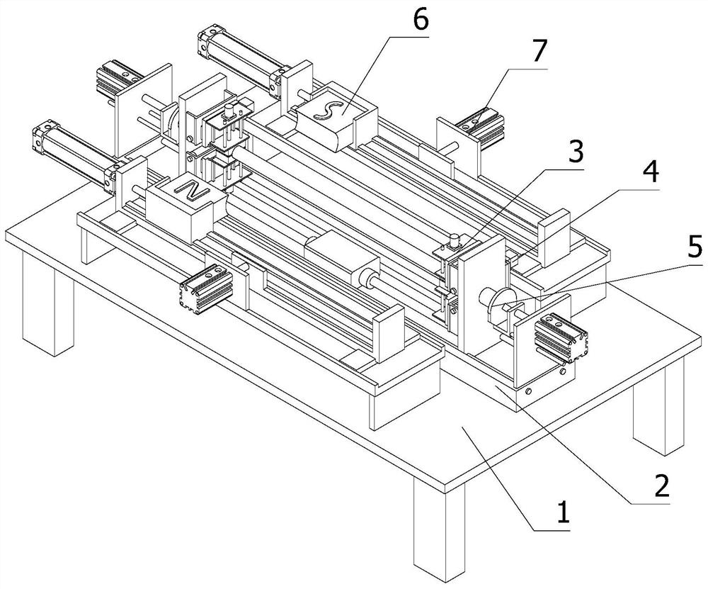
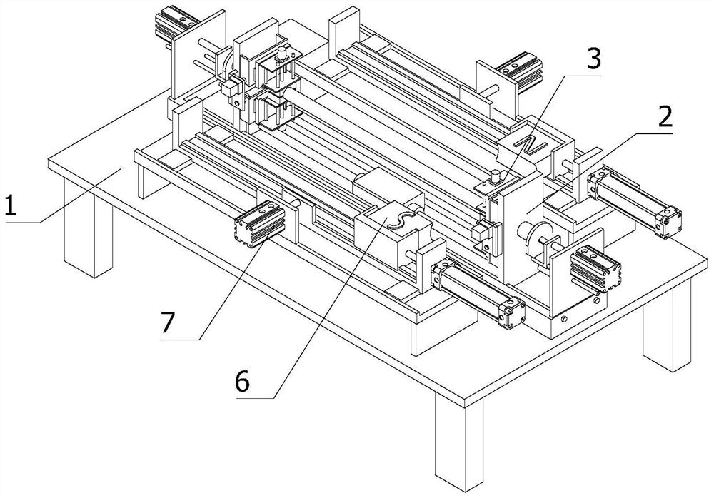
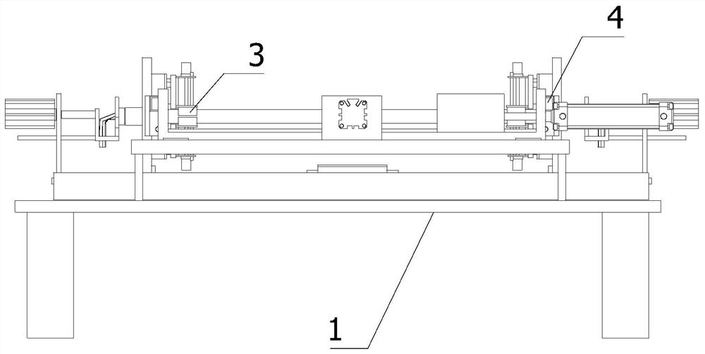
[0048] refer to Figure 1-Figure 4 A high-magnetic field transmission performance testing device for optical fibers is shown, including:

[0049] Rack 1;

[0050] The stretching driving mechanism 2 is horizontally arranged on the frame 1, and is used to provide driving force for stretching the optical fiber;

[0051] The optical fiber clamping mechanism 3 is provided with two groups, and the two groups of optical fiber clamping mechanisms 3 are respectively arranged on the two output ends of the stretching drive mechanism 2, and are used to clamp the two ends of the optical fiber so that the two ends of the optical fiber follow The two output ends of the stretching drive mechanism 2 move in opposite direc...


PUM


Abstract

The present invention relates to the technical field of optical fiber signal detection, in particular to a high-magnetic field transmission performance testing device for optical fibers, which includes: a frame; a stretching drive mechanism, which is horizontally arranged on the frame; Two sets of optical fiber clamping mechanisms are respectively set on the two output ends of the stretching drive mechanism; there are two sets of end push-out mechanisms, and two sets of optical fiber clamping mechanisms are respectively set on the two output ends of the stretching drive mechanism On the top, the terminal push-out mechanism is located between the output end of the stretching drive mechanism and the optical fiber clamping mechanism; the electrical signal connection mechanism; the magnetic field generating device; On both sides of the stretching drive mechanism, a strong magnetic field transmission performance testing device for optical fibers shown in the present invention can automatically stretch the installed optical fiber, and can comprehensively reflect the difference between the magnetic field and optical fiber signal transmission performance under different conditions. relationship between.

Description

technical field [0001] The invention relates to the technical field of optical fiber signal detection, in particular to a high magnetic field transmission performance detection device for optical fiber. Background technique [0002] Optical fiber, short for optical fiber, is a fiber made of glass or plastic that acts as a means of light transmission. The transmission principle is "total reflection of light". The transmission principle of optical fiber in optical fiber can be analyzed from two different viewpoints or theories, namely: wave theory and geometric optics ray theory. Wave theory is the benchmark theory for analyzing the principle of optical fiber light transmission. It starts from the basic equations that describe the behavior of electromagnetic waves—Maxwell's equations, and solves the wave equation that satisfies the initial conditions. This analysis method is suitable for any situation and can accurately describe the optical fiber transmission characteristics...

Claims


Application Information

Patent Timeline
Patent Type & Authority Patents(China)
IPC IPC(8): G01M11/00
CPCG01M11/30G01M11/33
Inventor 杨乐黄一霖磨唯彭舜杰蓝天宝刘博其他发明人请求不公开姓名
Owner GUANGXI POWER GRID CORP
Why Eureka
Try Eureka