

Sediment sampling device for water conservancy project
A water conservancy project and sampling device technology, applied in the direction of sampling devices, etc., can solve problems affecting water conservancy and irrigation, and achieve the effects of improving sediment sampling operations, increasing efficiency, and reducing sampling risks
- Summary
- Abstract
- Description
- Claims
- Application Information
AI Technical Summary
Problems solved by technology
Method used
Image

Examples
Embodiment 1
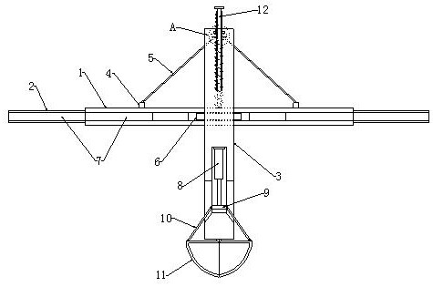
[0028] refer to Figure 1-3 and Figure 5 , a sediment sampling device for water conservancy projects, comprising a first crossbar 1 and a second crossbar 2, the inside of the first crossbar 1 is slidingly installed along its length direction with two symmetrically distributed second crossbars 2, And the ends of the two second crossbars 2 that are far away from each other extend to the outside of the first crossbar 1, and an adjustment mechanism is arranged between the first crossbar 1 and the two second crossbars 2, and the first crossbar 1 and the second crossbar The fronts of the two crossbars 2 are all provided with moving rails 7 along their lengthwise directions, and the mobile device 6 is slidably installed in the moving rails 7, and the front of the mobile device 6 is equipped with vertical bars 3 sliding in the vertical direction, and the vertical bars 3 Movable grooves are set inside the movable groove, the top inner wall of the movable groove is fixedly equipped wi...
Embodiment 2
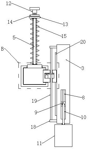
[0034] refer to figure 2 , Figure 4 and Figure 6 , the moving device 6 is provided with a mounting groove 24 inside, and the drive motor 21 is fixedly installed inside the mounting groove 24, the output shaft end of the drive motor 21 is fixedly connected with the main gear plate 22, and the top inner wall of the mounting groove 24 is rotatably mounted with a secondary gear disc 23, and the secondary gear disc 23 meshes with the main gear disc 22, and the back of the vertical bar 3 is fixedly connected with two symmetrically distributed mounting plates 18, and a threaded rod 19 is connected between the two mounting plates 18, and the threaded rod 19 It runs through the moving device 6 , and the threaded rod 19 and the pinion gear plate 23 are threaded and penetrated.
[0035] The back side of the vertical bar 3 is fixedly installed with a limit bar 20 along its height direction, and the side of the mobile device 6 near the vertical bar 3 is provided with a limit slot 25, ...
PUM
 Abstract
Description
Claims
Application Information