
Water meter shell pressure detection device and detection method

A detection device and water meter case technology, applied in the direction of measuring device, measuring fluid pressure, using stable tension/pressure to test material strength, etc., can solve the problem that the detection results are prone to incompleteness, inconvenient multi-point detection, and inability to adapt to different Standardized water meter detection and other issues, to achieve the effect of stable detection, stable clamping, and airtightness

Pending Publication Date: 2021-05-14
埃尔斯特仪表(南通)有限公司
View PDF0 Cites 0 Cited by
  • Summary
  • Abstract
  • Description
  • Claims
  • Application Information

AI Technical Summary

Problems solved by technology

[0003] The internal structure of the traditional water meter can be divided into three parts: the shell, the sleeve, and the inner core from the outside to the inside. The water meter shell is a component that is in direct contact with water. It cannot be put into use. Now some detection devices are designed for pressure detection, but the monitoring device can only adapt to a single type of water meter for detection, and cannot adapt to water meters of different specifications for detection. At the same time, the existing devices move vertically for single Point detection, it is inconvenient to adjust to different positions for multi-point detection, and the detection results are prone to incompleteness

Method used


Image

  • Water meter shell pressure detection device and detection method
  • Water meter shell pressure detection device and detection method
  • Water meter shell pressure detection device and detection method

Examples


Embodiment 1

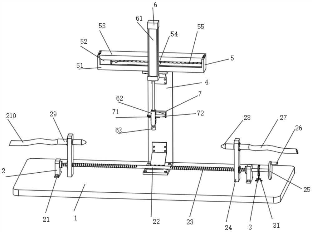
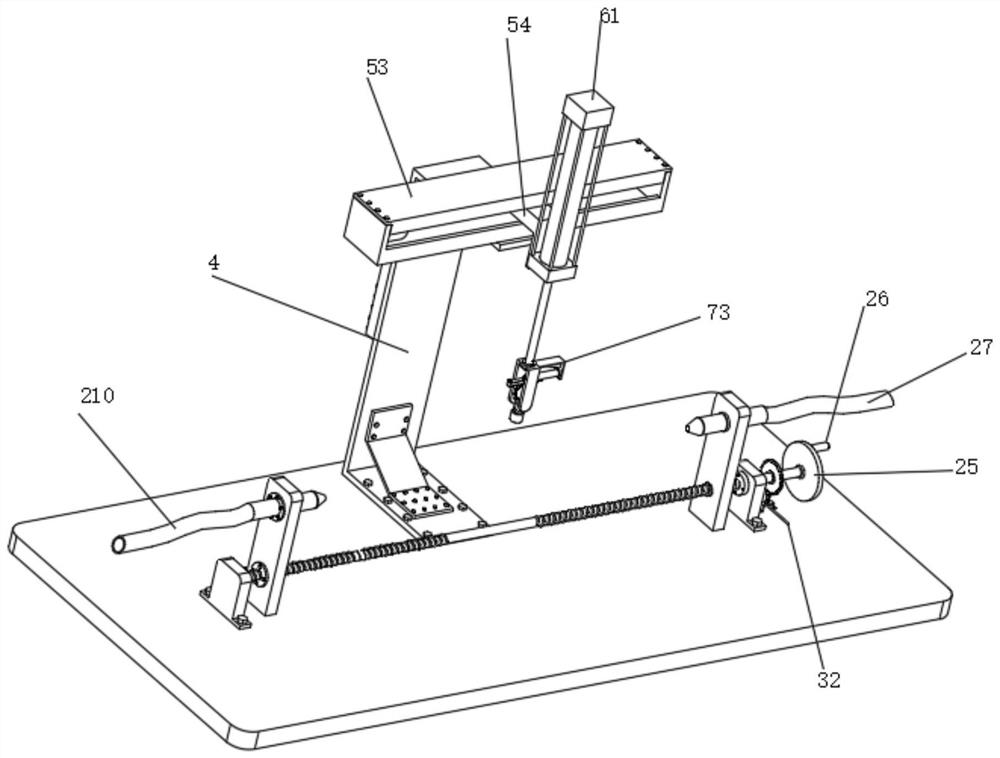
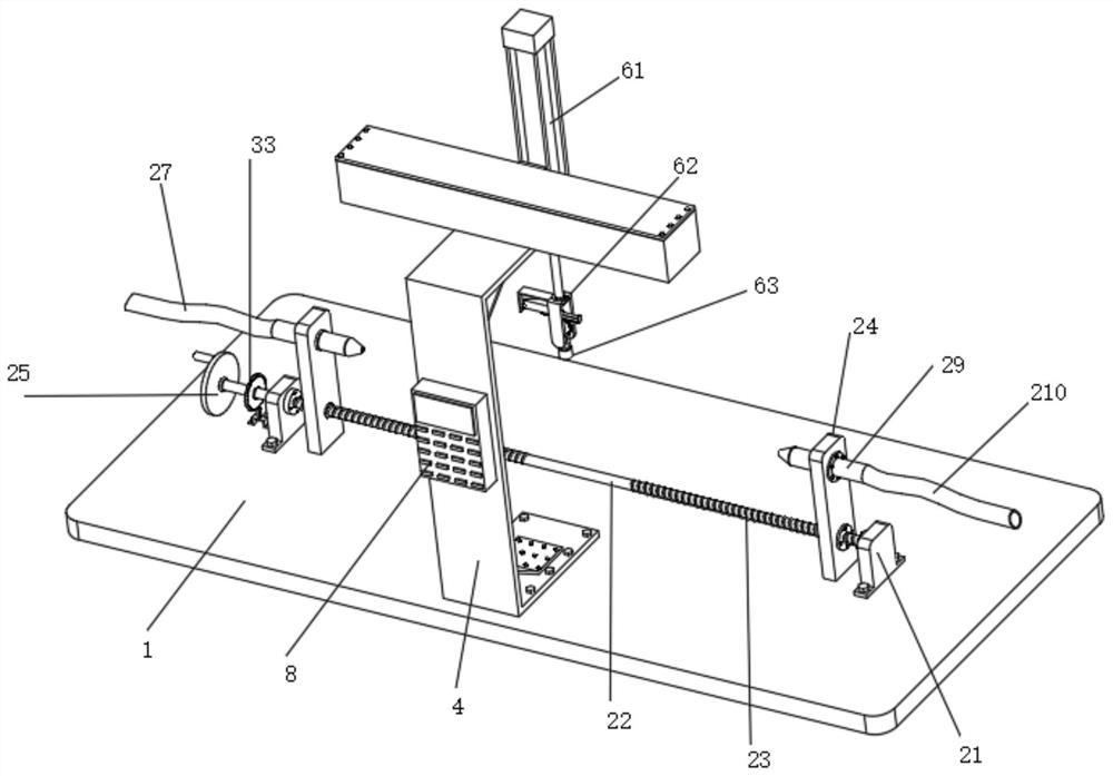
[0042] Such as figure 1 , 2 , 3, 6, and 8, a water meter casing pressure detection device includes a base 1, the top middle end of the base 1 is provided with a water meter clamping structure 2 for fixing the water meter, and the water meter clamping structure 2 includes a first convex Block 21, rotating rod 22, screw groove 23, slide plate 24, the first turntable 25, rocking bar 26, water inlet hose 27, rubber tapered pipe 28, horizontal pipe 29, water outlet hose 210 and tapered pipe 211, the first Convex block 21 is symmetrically fixedly installed on the top of base 1, and the first protruding block 21 is rotatably connected with rotating rod 22 by the bearing that is fixedly installed, and the right end of rotating rod 22 is fixedly connected with first rotating disc 25, and the first rotating disc 25 The outer edge of the side wall is fixedly connected with a rocking bar 26 for promoting the rotation of the first turntable 25, and the outer wall of the rocking bar 26 is ...


PUM


Abstract

The invention discloses a water meter shell pressure detection device and method, and relates to the field of water meter production equipment. The water meter shell pressure detection device comprises a base, and a water meter clamping structure used for fixing a water meter is arranged at the middle end of the top of the base; the water meter clamping structure comprises first convex blocks, a rotating rod, threaded grooves, a sliding plate, a first rotating disc, a rocker, a water inflow hose, a rubber conical pipe, a transverse pipe, a water outflow hose and a conical pipe; the first convex blocks are symmetrically and fixedly installed on the top of the base; the first convex blocks are rotationally connected with the rotating rod through fixedly installed bearings; the first rotating disc is fixedly connected to the right end of the rotating rod; the rocker used for pushing the first rotating disc to rotate is fixedly connected to the outer edge of the side wall of the first rotating disc; and threaded grooves are symmetrically formed in the positions, between the first convex blocks, of the rotating rod. With the water meter shell pressure detection device and detection method of the invention adopted, the water meter can be fixedly installed between the transverse pipes conveniently.

Description

technical field [0001] The invention relates to the field of water meter production equipment, in particular to a water meter casing pressure detection device and a detection method. Background technique [0002] A water meter is an instrument for measuring water flow. Most of them measure the cumulative flow of water. They are generally divided into two types: volumetric water meters and speed water meters. They originated in the United Kingdom. The development of water meters has a history of nearly two hundred years. , you should first estimate the size and flow range of the flow normally used, and then choose the water meter of the specification with the usual flow closest to the value as the first choice. [0003] The internal structure of the traditional water meter can be divided into three parts: the shell, the sleeve, and the inner core from the outside to the inside. The water meter shell is a component that is in direct contact with water. It cannot be put into u...

Claims


Application Information

Patent Timeline
IPC IPC(8): G01N3/12G01N3/02G01N3/04G01M13/00G01L11/00
CPCG01L11/00G01M13/00G01N3/02G01N3/04G01N3/12G01N2203/0019G01N2203/0044
Inventor 王小兵
Owner 埃尔斯特仪表(南通)有限公司
Learn More