Geometric calibration method of all-sky imager based on gradient descent method

An all-sky imager and gradient descent method, applied in the field of geometric calibration, can solve the problems of high precision, difficulty in re-calibration, inability to determine the position of pixels of all-sky images and geographic orientation information, etc., and achieve flexible geometric calibration. , the effect of fast and accurate geometric calibration

Pending Publication Date: 2021-05-14
POLAR RES INST OF CHINA +1
View PDF9 Cites 0 Cited by
  • Summary
  • Abstract
  • Description
  • Claims
  • Application Information

AI Technical Summary

Problems solved by technology

[0003] The traditional geometric calibration method of the all-sky auroral imager needs to use special calibration equipment under laboratory conditions to take pictures of specific landmarks by rotating the all-sky camera, and to obtain the relationship between the imaging radius and the zenith angle by fitting. relationship, the above geometric calibration method cannot determine the pixel position and geographic orientation information of the zenith in the all-sky image
In addition, during the actual use of the all-sky imager, due to imaging firmware (CCD, etc.), update of the optical lens, and equipment maintenance, the "object-image" relationship of the all-sky imager will change. For an all-sky auroral imager in the Arctic and Antarctic regions, for example, it is very difficult to recalibrate in the laboratory
On the other hand, in the existing geometric calibration method of the all-sky auroral imager based on star points, it is necessary to manually calculate the position of the zenith in the whole-sky image, and the process is complicated. Due to accidental errors, the number of star points used in fitting the relationship between imaging radius and zenith angle is small, and it is difficult to ensure high accuracy

Method used


Image

  • Geometric calibration method of all-sky imager based on gradient descent method
  • Geometric calibration method of all-sky imager based on gradient descent method
  • Geometric calibration method of all-sky imager based on gradient descent method

Examples


Embodiment 1

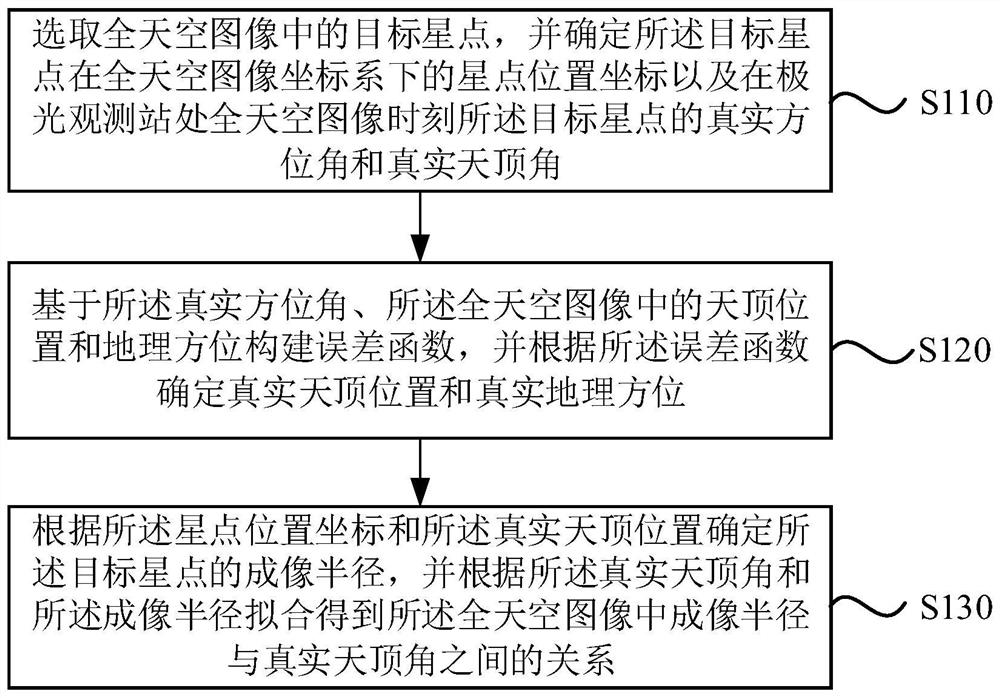
[0028] figure 1 It is a flowchart of a geometric calibration method for an all-sky imager based on the gradient descent method provided by Embodiment 1 of the present invention. This embodiment is applicable to fast and accurate geometric calibration of an all-sky imager at any location In the case of , the method can be executed by the geometric calibration device of the all-sky imager based on the gradient descent method, and the device can be implemented in the form of software and / or hardware. Specifically include the following steps:

[0029] S110. Select the target star point in the all-sky image, and determine the star point position coordinates of the target star point in the all-sky image coordinate system and the real azimuth angle of the target star point at the moment of the all-sky image at the aurora observation station and true zenith angles.

[0030] Wherein, a group of all-sky images is acquired by an all-sky imager, and a group of all-sky images includes on...

Embodiment 2

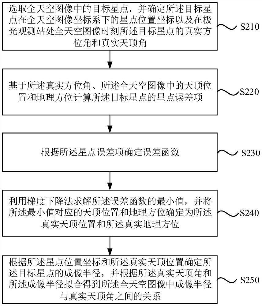
[0047] Figure 2A It is a flow chart of a geometric calibration method for an all-sky imager based on the gradient descent method provided by Embodiment 2 of the present invention. This embodiment is optimized based on the foregoing embodiments.

[0048] Correspondingly, the method in this embodiment specifically includes:

[0049] S210. Select the target star point in the all-sky image, and determine the star point position coordinates of the target star point in the all-sky image coordinate system and the real azimuth angle of the target star point at the moment of the all-sky image at the aurora observation station and true zenith angles.

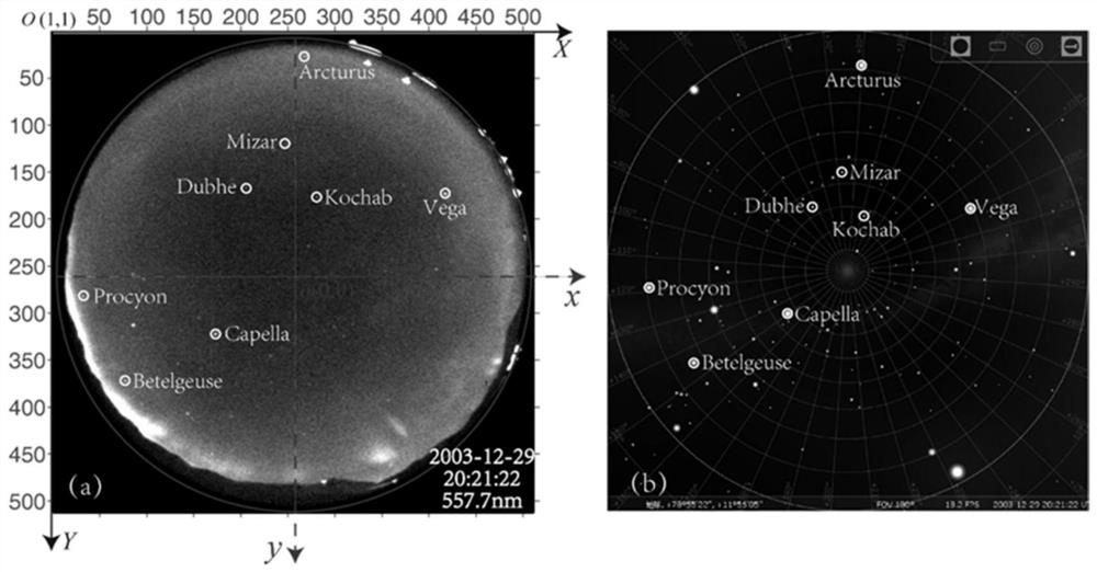
[0050] Specifically, select multiple all-sky images with clear star points, Figure 2B It is a schematic diagram of an exemplary all-sky image provided by an embodiment of the present invention and a star map corresponding to the shooting time of the whole-sky image at the Yellow River Station, see Figure 2B In the left figure in the...

Embodiment 3

[0084] image 3 A structural diagram of a geometric calibration device for an all-sky imager based on the gradient descent method provided by Embodiment 3 of the present invention. This embodiment is applicable to fast and accurate geometric calibration of an all-sky imager at any location Case.

[0085] like image 3 As shown, the geometric calibration device includes: a real data determination module 310, an error function construction module 320 and a geometric calibration determination module 330, wherein:

[0086] The real data determination module 310 is used to select the target star point in the all-sky image, and determine the star point position coordinates of the target star point in the all-sky image coordinate system and the target at the time of the all-sky image at the aurora observation station The true azimuth and true zenith angle of the star point;

[0087] An error function construction module 320, configured to construct an error function based on the t...


PUM


Abstract

The embodiment of the invention discloses a geometric calibration method of an all-sky imager based on a gradient descent method. The geometric calibration method comprises the following steps: selecting a target star point in an all-sky image, and determining star point position coordinates of the target star point in an all-sky image coordinate system and a real azimuth angle and a real zenith angle of the target star point at an aurora observation station at the moment of the all-sky image; constructing an error function based on the real azimuth angle and the zenith position and the geographic orientation in the all-sky image, and determining a real zenith position and a real geographic orientation according to the error function; and determining the imaging radius of the target star point according to the star point position coordinates and the real zenith position, and obtaining the relation between the imaging radius and the real zenith angle in the all-sky image through fitting according to the real zenith angle and the imaging radius. According to the technical scheme of the embodiment of the invention, geometric calibration can be quickly and accurately carried out on the all-sky imager without being limited by regions, and the geometric calibration of the all-sky imager is more flexible.

Description

technical field [0001] Embodiments of the present invention relate to the technical field of geometric calibration, and in particular to a geometric calibration method for an all-sky imager based on a gradient descent method. Background technique [0002] The all-sky imager is an important ground-based space environment optical observation equipment. The accurate "object image" optical geometric correspondence is to obtain the actual scale of the auroral structure, determine the projection transformation of the all-sky aurora image to geographic and geomagnetic coordinate systems, and realize The basis for joint observations of all-sky imagers and satellites, which is extremely important for the study of related space physical processes and mechanisms. [0003] The traditional geometric calibration method of the all-sky auroral imager needs to use special calibration equipment under laboratory conditions to take pictures of specific landmarks by rotating the all-sky camera, ...

Claims


Application Information

Patent Timeline
Patent Type & Authority Applications(China)
IPC IPC(8): G01V8/10G01V13/00
CPCG01V8/10G01V13/00
Inventor 胡泽骏李国君黄德宏韩冰李斌
Owner POLAR RES INST OF CHINA
Why Eureka
Try Eureka