
a compensation circuit

A compensation circuit and compensation current technology, which is applied in the electronic field, can solve problems such as adjusting bias current and deteriorating linearity of power amplifiers

Active Publication Date: 2021-09-28
GUANGZHOU HUIZHI MICROELECTRONICS
View PDF26 Cites 0 Cited by
  • Summary
  • Abstract
  • Description
  • Claims
  • Application Information

AI Technical Summary

Problems solved by technology

[0003] However, in the prior art, a fixed bias current is usually provided for the power amplifier to slow down the nonlinear distortion of the power amplifier; but as the input signal gradually becomes larger, the gain of the power amplifier will gradually decrease, and this method The bias current cannot be adjusted according to the size of the input signal, that is, the input signal reaches a certain level, and the gain presents a compression trend, resulting in a significant deterioration of the linearity of the power amplifier.

Method used


Image

  • a compensation circuit
  • a compensation circuit
  • a compensation circuit

Examples


Embodiment Construction

[0046] In order to make the purpose, technical solution and advantages of the present invention clearer, the present invention will be described in further detail below in conjunction with the accompanying drawings, and the described embodiments should not be considered as limiting the present invention, and those of ordinary skill in the art do not make any All other embodiments obtained under the premise of creative labor belong to the protection scope of the present invention.

[0047] In the case of no conflict, the embodiments in the present application and the features in the embodiments can be combined arbitrarily with each other. Although a logical order is shown in the flowcharts, in some cases the steps shown or described may be performed in an order different from that shown or described herein.

[0048] Unless otherwise defined, all technical and scientific terms used herein have the same meaning as commonly understood by one of ordinary skill in the technical fiel...


PUM


Abstract

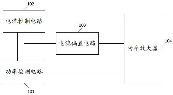
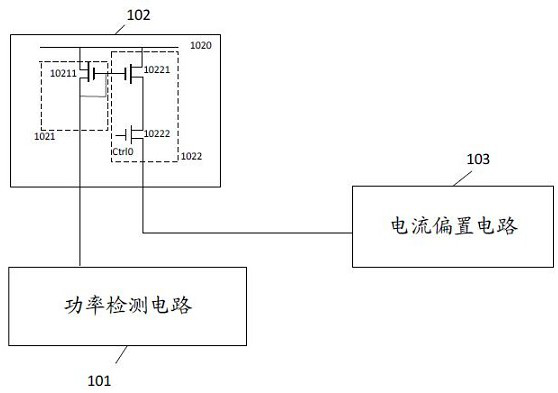
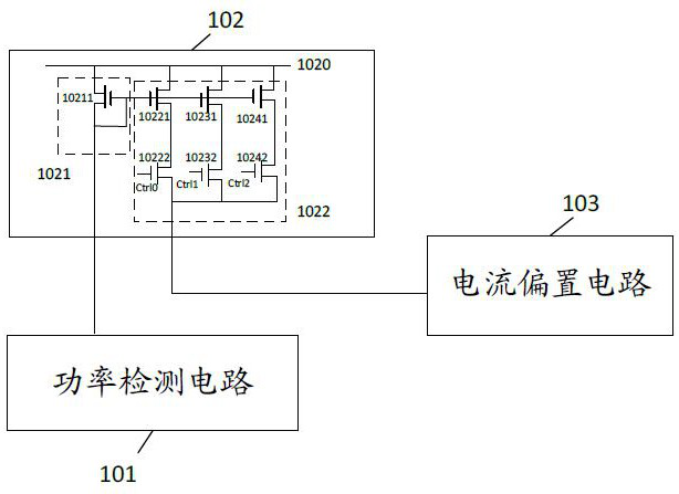
The invention provides a compensation circuit, including: a power amplifier, a current bias circuit, a power detection circuit and a current control circuit; the power detection circuit is connected with the power amplifier, and is used to detect the voltage amplitude of the radio frequency input signal of the power amplifier, and the When the voltage amplitude satisfies the preset condition, a reference current is output; the current control circuit is respectively connected with the power detection circuit and the current bias circuit, and is used to receive the reference current output by the power detection circuit, and output the compensation current to the current bias based on the reference current circuit; a current bias circuit, connected to the current control circuit and the power amplifier respectively, for receiving the compensation current output by the current control circuit and generating a DC bias current, and outputting the compensation current and the DC bias current to the power amplifier; the power amplifier, It is connected with the current bias circuit and is used for receiving the compensation current and the DC bias current, and based on the compensation current and the DC bias current, the power of the radio frequency input signal is amplified.

Description

technical field [0001] The invention relates to the field of electronic technology, in particular to a compensation circuit. Background technique [0002] With the development of 5G communication, high-bandwidth and high-linear power amplifier (Power Amplifier, PA) plays an increasingly important role. The nonlinear distortion of power amplifier has become a serious problem in 5G wireless communication system, which affects The linear amplification capability and signal efficiency of the power amplifier. [0003] However, in the prior art, a fixed bias current is usually provided for the power amplifier to slow down the nonlinear distortion of the power amplifier; but as the input signal gradually becomes larger, the gain of the power amplifier will gradually decrease, and this method The magnitude of the bias current cannot be adjusted according to the magnitude of the input signal, that is, the input signal reaches a certain level, and the gain presents a compression tren...

Claims


Application Information

Patent Timeline
Patent Type & Authority Patents(China)
IPC IPC(8): H03F3/24H03F1/32
CPCH03F3/245H03F1/32H03F2200/451H03F1/3205H03F1/0272H03F1/303H03F2200/18H03F3/21
Inventor 彭振飞苏强
Owner GUANGZHOU HUIZHI MICROELECTRONICS
Learn More