
Electronic atomization equipment

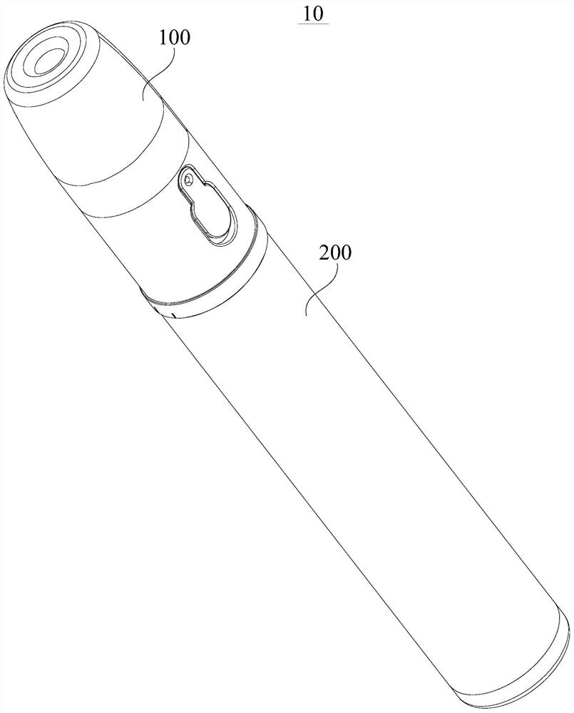
An electronic atomization and equipment technology, applied in the direction of tobacco, etc., can solve the problems of low reuse rate of parts, impossible disassembly, and use safety risks.

Pending Publication Date: 2021-05-18
SHENZHEN AEROSOL TECH RES CO LTD
View PDF0 Cites 0 Cited by
  • Summary
  • Abstract
  • Description
  • Claims
  • Application Information

AI Technical Summary

Problems solved by technology

[0004] First, the atomization mechanism and the power supply mechanism adopt an integrated design, and the two cannot be disassembled in normal use. At the same time, the oil cup and the shell of the atomization mechanism are fixedly connected or fixed or integrated, and it is impossible to disassemble , when the atomization medium in the oil cup is used up, the entire electronic atomization device fails, also known as a disposable electronic atomization device, because the atomization medium in the oil cup is directly connected to the atomization chamber of the housing Since the atomization chamber is also connected with the air, this will cause the atomization medium in the oil cup to be oxidized and deteriorate. Adding atomization medium to the oil cup will cause risks, and the atomization mechanism and power supply mechanism It adopts an integrated design, so it can only be used as a disposable electronic atomization device
[0005] Second, the atomization mechanism and the power supply mechanism adopt a detachable design, and the two can be disassembled during use. When the atomization medium in the oil cup of the atomization mechanism is used up, the entire atomization mechanism will be replaced directly, that is, a disposable atomizer. The deep-rooted problem of its replacement reason is the same as the problem that the atomization medium is easily oxidized in the disposable electronic atomization device, all because the atomization medium in the oil cup - the atomization chamber - the air is three If the atomization medium in the oil cup is connected to each other for a long time, it is very easy to cause the atomization medium in the oil cup to be oxidized and polluted. If the atomization medium is added to the oil cup, the fresh atomization medium will also mix with the easily polluted atomization medium in the oil cup , leading to product quality and safety risks
[0006] Third, the atomization medium, atomization chamber and air in the oil cup are connected to each other for a long time, and the factors of oxidative pollution in the air enter directly from the atomization chamber into the oil storage chamber in the oil cup for a long time. In this way, It will cause the existing atomizing medium in the atomizing chamber to cause oxidation pollution. No matter how it is used, the atomized substance polluted by oxidation will remain and adhere to the oil cup more or less. There is an oil filling device for the oil cup of the atomizing mechanism. The electronic atomization equipment design of the hole and hole plug, the fresh atomization medium injected through the oil injection hole will be mixed and polluted by the oxidized and polluted "old e-liquid" in the oil cup
[0007] To sum up, based on the problem that the atomizing medium in the oil cup is easily oxidized and polluted, for the first design and the second design, the electronic atomization device is designed to be disposable and the atomization mechanism is designed to be disposable, which will affect the material It causes great waste, that is, there is a problem of low reuse rate of parts in the overall design. Further, for the third design, if the atomization medium is added more times, it will bring serious safety risks in use

Method used


Image

  • Electronic atomization equipment
  • Electronic atomization equipment
  • Electronic atomization equipment

Examples


Embodiment Construction

[0037] In order to facilitate the understanding of the present invention, the present invention will be described more fully below with reference to the associated drawings. Preferred embodiments of the invention are shown in the accompanying drawings. However, the present invention can be embodied in many different forms and is not limited to the embodiments described herein. On the contrary, the purpose of providing these embodiments is to make the disclosure of the present invention more thorough and comprehensive.

[0038]It should be noted that when an element is referred to as being “fixed” to another element, it can be directly on the other element or there can also be an intervening element. When an element is referred to as being "connected to" another element, it can be directly connected to the other element or intervening elements may also be present. The terms "vertical," "horizontal," "left," "right," and similar expressions are used herein for purposes of illu...


PUM


Abstract

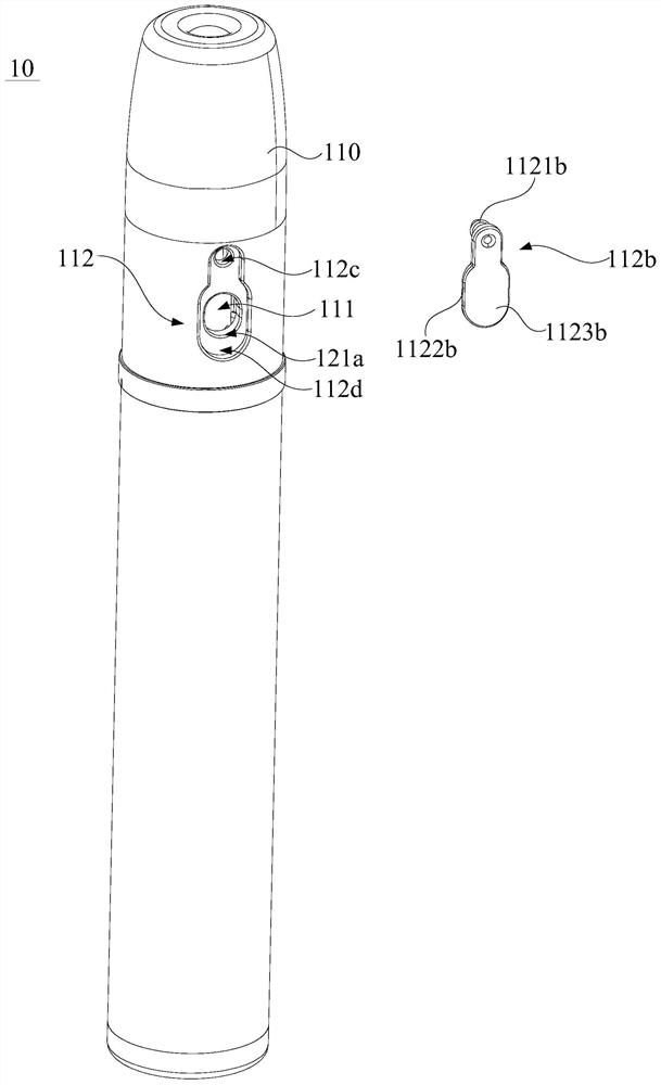
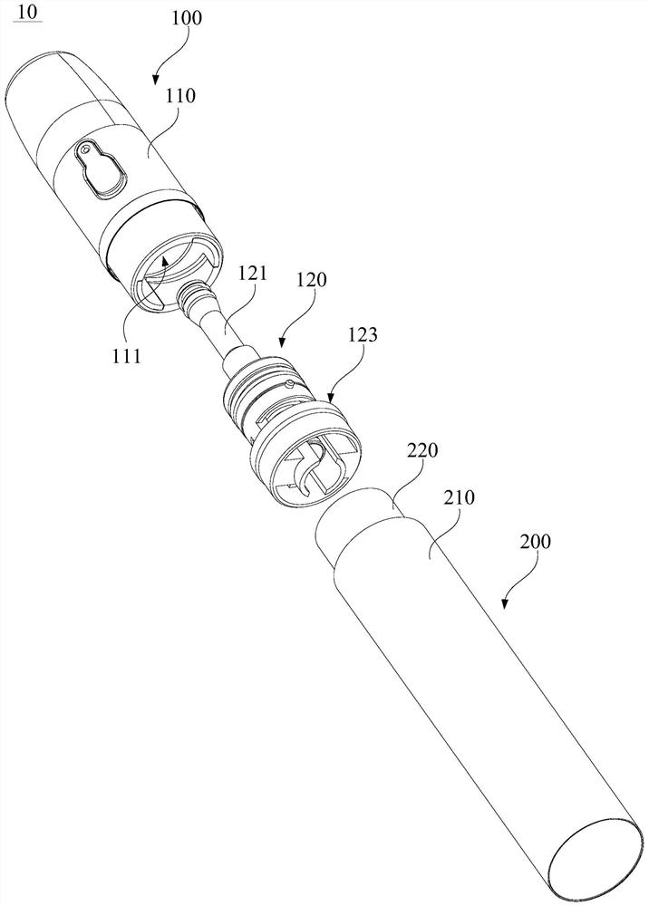
The invention provides electronic atomization equipment. The electronic atomization equipment comprises an atomization mechanism and a power source mechanism connected with the atomization mechanism. The atomization mechanism comprises a shell and an atomization assembly. The shell is provided with an oil storage cavity and an oil injection area communicated with the oil storage cavity, and an oil way cutting-off structure is arranged at the communicating position of the atomization assembly and the oil storage cavity. A fresh atomizing medium can be repeatedly injected into the oil storage cavity through the oil injection area, and the fresh atomizing medium which is repeatedly injected is contained in the oil storage cavity which is in a clean state for a long time, so that the quality-guaranteeing, anti-oxidation and anti-pollution effects of the electronic atomization equipment are better. On the premise of the same atomizing medium and on the premise of ensuring that the environment in the oil storage cavity and the atomizing medium reach the industrial quality safety standard, the number of times of continuously injecting the atomizing medium for the electronic atomization equipment is at least ten times that for the traditional electronic atomization equipment, so that the repeated utilization rate of parts can be greatly improved, the use safety risk problem can be remarkably reduced, and the equipment is more economical and environment-friendly.

Description

technical field [0001] The invention relates to the technical field of electronic atomization, in particular to an electronic atomization device. Background technique [0002] For electronic atomization equipment, it generally includes an atomization mechanism and a power supply mechanism. The power supply mechanism is used to supply power to the atomization mechanism. It is connected with the atomization chamber and directly provides the atomization medium, such as smoke oil, to the electric heating element in the atomization chamber. After the electric heating element is energized and heated, it is used to atomize the atomization medium, and then mixes air to generate aerosol. [0003] In traditional electronic atomization equipment, the design of the oil cup of the atomization mechanism generally adopts the following three forms: [0004] First, the atomization mechanism and the power supply mechanism adopt an integrated design, and the two cannot be disassembled in norm...

Claims


Application Information

Patent Timeline
Patent Type & Authority Applications(China)
IPC IPC(8): A24F40/46A24F40/42A24F40/10
CPCA24F40/10A24F40/42A24F40/46
Inventor 彭世键
Owner SHENZHEN AEROSOL TECH RES CO LTD
Learn More