
Cleaning assembly and crude oil filter element cleaning device

A technology for cleaning devices and filters, applied in filter regeneration, filtration separation, chemical instruments and methods, etc., can solve problems such as low efficiency of cleaning methods

Pending Publication Date: 2021-05-18
张殿龙
View PDF0 Cites 0 Cited by
  • Summary
  • Abstract
  • Description
  • Claims
  • Application Information

AI Technical Summary

Problems solved by technology

[0004] The purpose of the present invention is to provide a cleaning assembly and a crude oil filter element cleaning device to solve the technical problem of low efficiency of the existing crude oil filter element cleaning method in the prior art; the preferred among many technical solutions provided by the present invention The many technical effects that the technical solution can produce are detailed in the following

Method used


Image

  • Cleaning assembly and crude oil filter element cleaning device
  • Cleaning assembly and crude oil filter element cleaning device
  • Cleaning assembly and crude oil filter element cleaning device

Examples


Embodiment 1

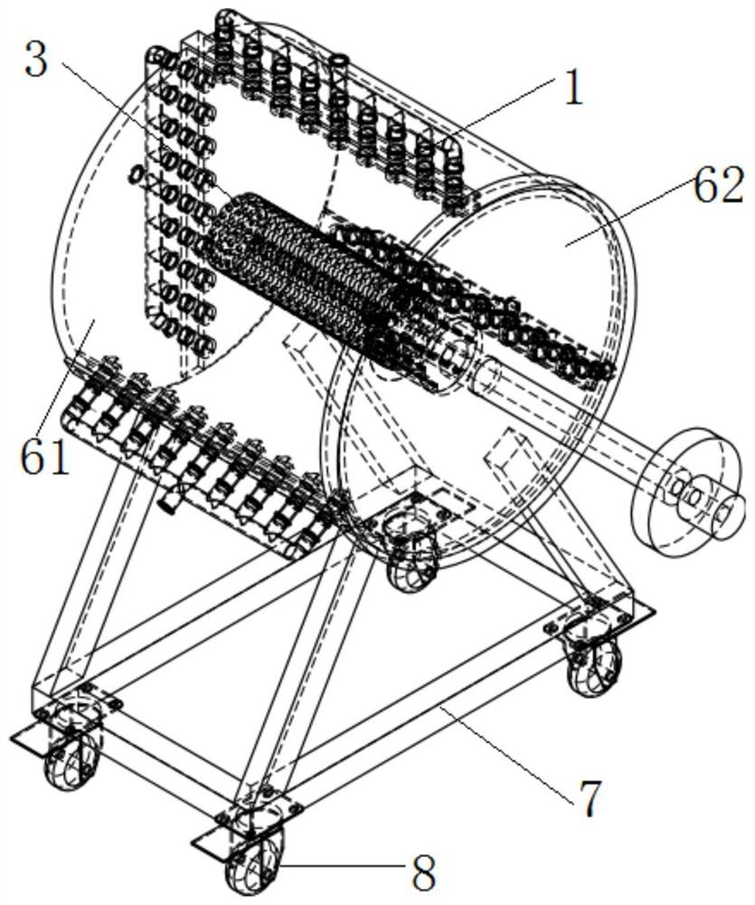
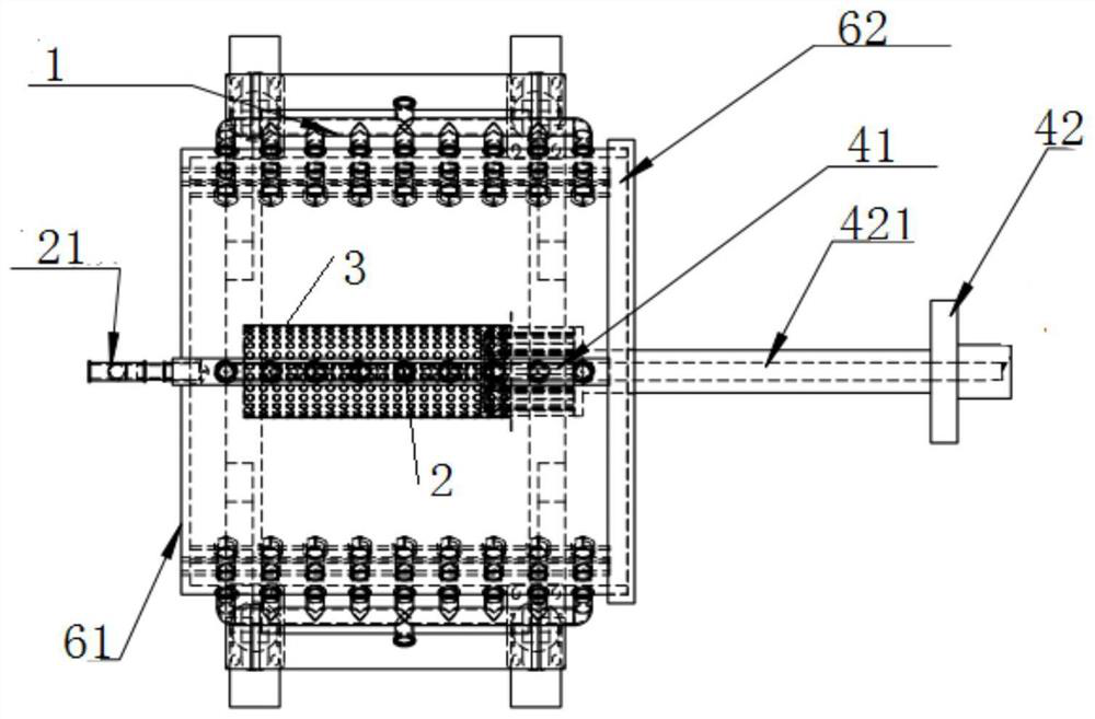
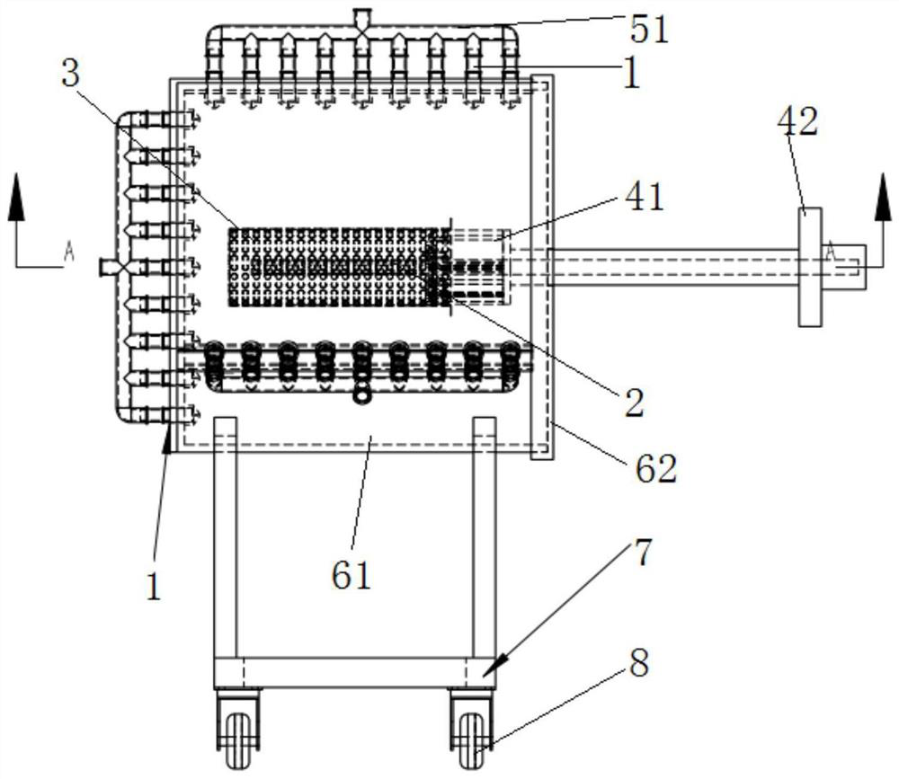
[0039] Such as Figure 1-Figure 8 As shown, this embodiment provides a cleaning assembly, including a fixing mechanism and a spraying mechanism, wherein: the fixing mechanism is detachably connected to the filter element 3, and the spraying mechanism includes an outer spray nozzle 1 capable of spraying high-pressure cleaning fluid and / or the inner spray nozzle 2, the outer spray nozzle 1 is located on the periphery of the fixing mechanism for spraying the outer wall of the filter element 3; the inner spray nozzle 2 extends into the filter element 3 on the fixing mechanism for spraying the inner wall of the filter element 3 .

[0040] In order to improve the cleaning effect of the filter element 3, see Figure 1-Figure 4 As shown, the spray mechanism in this embodiment includes an outer spray nozzle 1 and an inner spray nozzle 2 capable of spraying high-pressure cleaning liquid, and the outer spray nozzle 1 is located at the periphery of the fixing mechanism for spraying the ...

Embodiment 2

[0052] see figure 1 , Figure 7 with Figure 8 As shown, this embodiment provides a crude oil filter element cleaning device, including a barrel body and the above-mentioned cleaning assembly, the outer spray nozzle 1 is located on the inner wall of the barrel, and the fixing mechanism and the inner spray nozzle 2 are located in the barrel. The liquid inlet main pipe 52 is located at the periphery of the staving, and the water diversion main pipe is located inside or outside the staving.

[0053] The crude oil filter element cleaning device of this embodiment is set as the structure of the barrel, the cleaning assembly is arranged in the barrel, and the filter element 3 connected in the barrel is sprayed by a fixing mechanism, and the high-pressure cleaning liquid is sprayed in the barrel , and the cleaned dirty liquid is located in the bucket body, preventing the dirty liquid from flowing out to the cleaning site, and while effectively cleaning the filter element 3, it ensu...


PUM


Abstract

The invention provides a cleaning assembly and a crude oil filter element cleaning device, relates to the technical field of crude oil treatment equipment, and solves the technical problem that an existing crude oil filter element cleaning mode is low in efficiency. The cleaning assembly comprises a fixing mechanism and a spraying mechanism, the fixing mechanism is detachably connected with the filter element, the spraying mechanism comprises an outer spraying nozzle and / or an inner spraying nozzle capable of spraying high-pressure cleaning liquid, and the outer spraying nozzle is located on the periphery of the fixing mechanism and used for spraying and washing the outer wall of the filter element; and the inner spraying nozzle extends into the filter element positioned on the fixing mechanism and is used for spraying and washing the inner wall of the filter element. According to the device, the filter element of the crude oil filter can be detached and then connected to the fixing mechanism, the outer wall and / or the inner wall of the filter element are / is sprayed through high-pressure cleaning liquid sprayed by the outer spraying nozzles located on the periphery of the filter element and / or the inner spraying nozzles extending into the filter element, the filter element can be efficiently washed, labor force and cost are saved, repeated use of the filter element can be effectively guaranteed, safety and reliability are achieved, and the filter element is not damaged.

Description

technical field [0001] The invention relates to the technical field of crude oil processing equipment, in particular to a cleaning component and a crude oil filter element cleaning device. Background technique [0002] Crude oil pipeline filter is one of the very important equipments in the process of crude oil gathering and transportation. It plays a very important role in protecting the normal operation of the oil pump. It has the characteristics of simple structure, convenient disassembly and large consumption. [0003] The applicant finds that the prior art has at least the following technical problems: the existing crude oil filter element is difficult to clean, and there is no special cleaning equipment. At present, in the actual work on site, the cleaning of the filter element is usually done by primitive methods such as burning and beating, resulting in the filter being easily damaged, having a short service life, frequent replacement, increasing the workload of the ...

Claims


Application Information

Patent Timeline
IPC IPC(8): B01D41/04
CPCB01D41/04
Inventor 张殿龙宋家喜王刚王峰王建宁骆世杰鄢仁生顾明刘敏达樊保锋文伟张宝金杨瑞张雷侯广典赵文
Owner 张殿龙
Learn More