
Liquid-liquid centrifugal equipment convenient for liquid separation for bioengineering

A technology of liquid separation and bioengineering, which is applied in the direction of centrifuges, etc., can solve the problems of incomplete liquid separation, affecting the effect of liquid separation, and requiring extremely high operating proficiency

Inactive Publication Date: 2021-05-18
耿慧
View PDF6 Cites 1 Cited by
  • Summary
  • Abstract
  • Description
  • Claims
  • Application Information

AI Technical Summary

Problems solved by technology

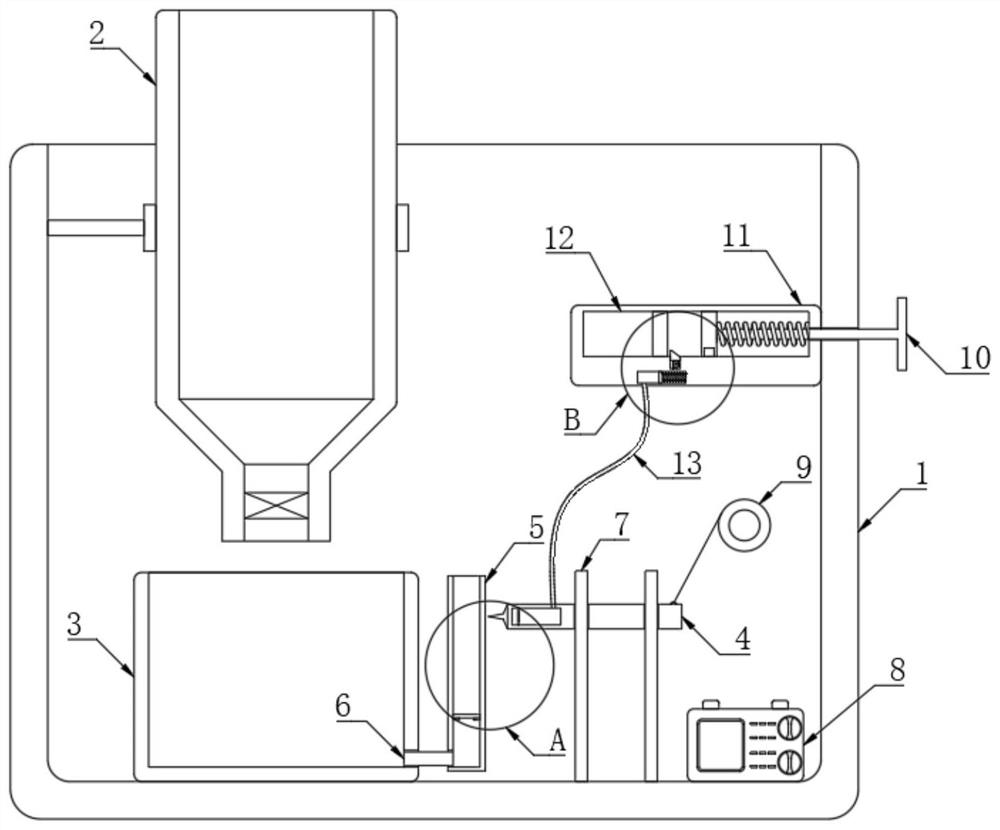
[0003] When the existing centrifuge equipment separates the liquid after the liquid is stratified, part of the staff directly sucks out the upper liquid with a syringe, and then separates the upper liquid from the lower liquid. This method requires the staff to operate proficiently. Extremely high, if there is a slight error, it may appear that part of the lower liquid is pumped out together or the upper liquid is not completely pumped out, thus affecting the separation effect of the liquid; The scale line is used to judge whether the liquid is released more or less, and the release of liquid is stopped when the lower liquid is completely released. In this way, in actual operation, because people are not necessarily in a completely horizontal state when observing the scale line with the naked eye, and the light through the centrifuge tube Refraction will occur. Therefore, when people squint at the centrifuge tube, the liquid level of the internal solution observed through the centrifuge tube does not match the actual scale line, and it is also prone to incomplete liquid separation or mixing of the upper liquid and the lower liquid. Therefore, It is necessary to design a kind of bioengineering liquid-liquid centrifugal equipment that is convenient for liquid separation to solve the above problems

Method used


Image

  • Liquid-liquid centrifugal equipment convenient for liquid separation for bioengineering
  • Liquid-liquid centrifugal equipment convenient for liquid separation for bioengineering
  • Liquid-liquid centrifugal equipment convenient for liquid separation for bioengineering

Examples


Embodiment Construction

[0025] The following will clearly and completely describe the technical solutions in the embodiments of the present invention with reference to the accompanying drawings in the embodiments of the present invention. Obviously, the described embodiments are only some, not all, embodiments of the present invention.

[0026] In describing the present invention, it should be understood that the terms "upper", "lower", "front", "rear", "left", "right", "top", "bottom", "inner", " The orientation or positional relationship indicated by "outside", etc. is based on the orientation or positional relationship shown in the drawings, and is only for the convenience of describing the present invention and simplifying the description, rather than indicating or implying that the referred device or element must have a specific orientation, so as to Specific orientation configurations and operations, therefore, are not to be construed as limitations on the invention.

[0027] refer to Figure ...


PUM


Abstract

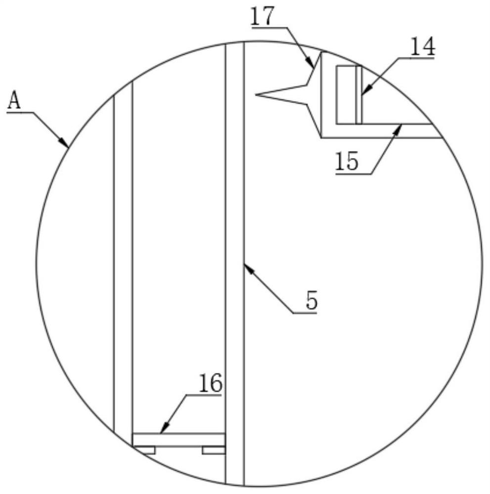
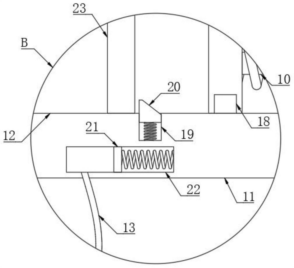
The invention discloses liquid-liquid centrifugal equipment which comprises a mounting box, wherein a centrifugal tube is fixedly connected to the inner wall of the mounting box, a liquid receiving box is fixedly connected to the inner bottom of the mounting box, and an electromagnetic valve is arranged at the bottom of the centrifugal tube; a control mechanism used for controlling the electromagnetic valve to be opened and closed is arranged in the mounting box, the control mechanism comprises a communication box arranged in the mounting box, the communication box communicates with the liquid receiving box through a connecting pipe, and a magnetic floating piece is connected to the inner wall of the communication box in a sealed and sliding mode; the bottom in the mounting box is fixedly connected with a power supply; and a moving plate is arranged in the mounting box, a control cavity is formed in the moving plate, and a magnetic piston is connected to the inner wall of the control cavity in a sealed and sliding mode. The electromagnetic valve can be automatically viewed when lower-layer liquid completely flows out, so that the lower-layer liquid is separated from upper-layer liquid, and the situation that the lower-layer liquid is mixed with the upper-layer liquid is avoided.

Description

technical field [0001] The invention relates to the technical field of bioengineering centrifugal equipment, in particular to a liquid-liquid centrifugal equipment used in bioengineering to facilitate liquid separation. Background technique [0002] Bioengineering is a method of manipulating genetic material, modifying organisms or their functions in a targeted manner, creating new species with ultra-distant traits in a short period of time, and then using appropriate bioreactors to treat such "engineering bacteria" or "engineering cell lines" It is an emerging technology to carry out large-scale culture to produce a large number of useful metabolites or to exert their unique physiological functions. In the process of bioengineering experiments, it is often necessary to centrifuge some cell fluids and other pharmaceuticals, while the existing centrifugal equipment There are the following problems. [0003] When the existing centrifuge equipment separates the liquid after th...

Claims


Application Information

Patent Timeline
IPC IPC(8): B04B11/05B04B13/00
CPCB04B11/05B04B13/00
Inventor 耿慧
Owner 耿慧
Learn More