Switch cabinet manufacturing device and switch cabinet manufactured through device

A technology for preparing devices and switch cabinets, which is applied in the cooling/ventilation of substation/switchgear, details of substation/switch arrangement, feeding device, etc., and can solve the problem of no buffer device, metal plate position offset, and no metal plate Issues such as limits and fixtures

Active Publication Date: 2021-05-18
STATE GRID SICHUAN ELECTRIC POWER
View PDF10 Cites 0 Cited by
  • Summary
  • Abstract
  • Description
  • Claims
  • Application Information

AI Technical Summary

Problems solved by technology

[0004] The present invention provides a switchgear preparation device and the switchgear, which can effectively solve the problem that the switchgear forming device proposed in the above background technology is not equipped with limiting and fixing devices for metal plates when stamping and forming the switchgear. The buffer device caused the position of the metal plate to shift when stamping the metal plate, which affected the stamping effect, resulting in the failure of the stamped product and resulting in product waste.

Method used


Image

  • Switch cabinet manufacturing device and switch cabinet manufactured through device
  • Switch cabinet manufacturing device and switch cabinet manufactured through device
  • Switch cabinet manufacturing device and switch cabinet manufactured through device

Examples


Embodiment 1

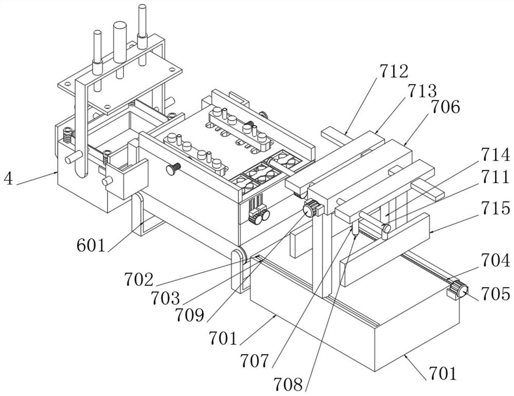
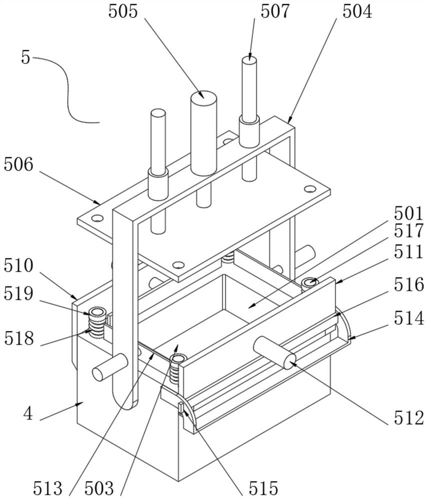
[0063]Example 1: Such asFigure 1-7 As shown, the present invention provides a technical solution, a switchgear preparation device including a stamping die 4, a molded assembly 5 is mounted on the side of the stamped lower mold 4;

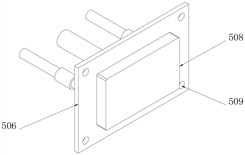
[0064]The forming assembly 5 includes a press cavity 501, a supporting hydraulic cylinder 502, a molded launch plate 503, a U-shaped support rod 504, a lower pressure hydraulic cylinder 505, a lower pressure molding plate 506, a guide connection rod 507, a lower pressure molded block 508, a guide hole 509, fixed mounting plate 510, rotating the mounting plate 511, clamping electric push rod 512, clamping plate 513, curved fixing frame 514, fixing hole 515, limit rod 516, guide post 517, cushion spring 518 and buffer pad 519;

[0065]The stamping cavity 501 is opened in the center of the stamper lower mold 4, and the stamping cavity 501 is sidedly fixedly mounted, and the support cylinder 502 is mounted. The top end of the support cylinder 502 is welded to the m...

Embodiment 2

[0077]Example 2: Such asFigure 8-13As shown, the present invention provides a technical solution, a switchgear, including a cabinet 1, a connecting assembly 2 on the cabinet 1;

[0078]The connecting assembly 2 includes a connection port 201, a slide 202, a slide groove 203, a sealing plate 204, a slide plate 205, a T-type fixing block 206, a connecting plate 207, an inverse port 208, a fixed connection block 209, and a rotating connection block 210, placement The cartridge 211, the support base 212, the fixed column 213, the cartridge 214, and the card 215;

[0079]The central portion of the cabinet 1 is sided there is a connection port 201, and the interior end of the cabinet 1 is located at the position of the connecting port 201, and the inner side of the cabinet 1 is located at both sides of the placement groove 202, and the slide groove 203 is opened. The inner side of the placing slot 202 is slidably mounted, and the sealing plate 204 is welded from one end of the placement groove ...


PUM


Abstract

The invention discloses a switch cabinet manufacturing device and a switch cabinet manufactured through the device. A forming assembly is installed at one side of a stamping lower die, a forming push-out plate is welded to the top end of a supporting hydraulic cylinder, U-shaped supporting rods are fixedly installed at the two ends of the stamping lower die, downward-pressing hydraulic cylinders are installed at the bottom ends of the U-shaped supporting rods, and downward-pressing forming plates are welded to the bottom ends of the downward-pressing hydraulic cylinders. A downward-pressing forming block is welded to the bottom end of each downward-pressing forming plate, a guide hole is formed at the top end of each downward-pressing forming plate, a limiting rod is embedded and installed at the inner side of a fixing hole, and the downward-pressing forming plates and the downward-pressing forming blocks are pressed downwards to press a metal plate into a stamping cavity, so that shaping of an outer metal shell of a switch tube is completed. The metal plate is limited through multiple clamping plates, the situation that the stamping effect is affected due to the fact that the position of the metal plate deviates is avoided, and when the metal plate is stamped, through a buffer spring and a buffer gasket, instant downward pressing force is relieved, and deformation abnormity caused when the metal plate is pressed downwards due to excessive downward pressing force is avoided.

Description

Technical field[0001]The present invention relates to the technical field of ring network switching cabinet, in particular a switchgear preparation device and a switchgear.Background technique[0002]The ring cabinet is a set of high-pressure switching equipment in the steel plate metal cabinet or is used as an electrical equipment for assembled space network power supply units. The core part uses a load switch and a fuse, which has simple structure, small size, low price. Improve the advantages of power supply parameters and performance and power supply safety, it is widely used in distribution stations and box substations such as urban residential communities, high-rise buildings, large-scale public buildings, factory enterprises and other load centers.[0003]However, when the switchgear molding device in the market is stamped to the switchgear, the limit and fixing device of the metal plate is not provided. At the same time, the cushioning device is not provided, resulting in an off...

Claims


Application Information

Patent Timeline
Patent Type & Authority Applications(China)
IPC IPC(8): B21D37/10B21D43/00B21D55/00B23K26/38B23P23/04H02B1/30H02B1/56
CPCB21D37/10B21D43/003B21D55/00B23K26/38B23P23/04H02B1/30H02B1/565
Inventor 郭家骏
Owner STATE GRID SICHUAN ELECTRIC POWER
Why Eureka
Try Eureka