Stamping device for mechanical equipment manufacturing

A technology of stamping device and buffer device, applied in the field of stamping device for mechanical equipment manufacturing, can solve the problems of low stamping efficiency, small scope of applicability, waste of processing equipment, etc., to improve quality and effect, wide range of applicability, and improved stamping effect of effect

Inactive Publication Date: 2020-11-03
李登进
View PDF1 Cites 0 Cited by
  • Summary
  • Abstract
  • Description
  • Claims
  • Application Information

AI Technical Summary

Problems solved by technology

[0004] However, the above-mentioned device still has the following problems in use: first, the device can only stamp specific stamping parts, and cannot stamp stamping parts with different requirements, resulting in a small range of applicability. When the stamping parts are stamped, the position of the stamping parts is prone to shift, resulting in poor stamping effect, which will not only waste the processing equipment and increase a certain cost, but also the quality of the stamped parts is poor, which cannot meet the requirements and the qualified rate of finished products is low , resulting in extremely low stamping efficiency

Method used


Image

  • Stamping device for mechanical equipment manufacturing
  • Stamping device for mechanical equipment manufacturing
  • Stamping device for mechanical equipment manufacturing

Examples


Embodiment Construction

[0028] In order to make the object, technical solution and advantages of the present invention more clear, the present invention will be further described in detail below in conjunction with the accompanying drawings and embodiments. It should be understood that the specific embodiments described here are only used to explain the present invention, not to limit the present invention.

[0029] In describing the present invention, it should be understood that the terms "longitudinal", "transverse", "upper", "lower", "front", "rear", "left", "right", "vertical", The orientations or positional relationships indicated by "horizontal", "top", "bottom", "inner", "outer", etc. are based on the orientations or positional relationships shown in the drawings, and are only for the convenience of describing the present invention, rather than indicating or It should not be construed as limiting the invention by implying that a referenced device or element must have a particular orientation,...


PUM


Abstract

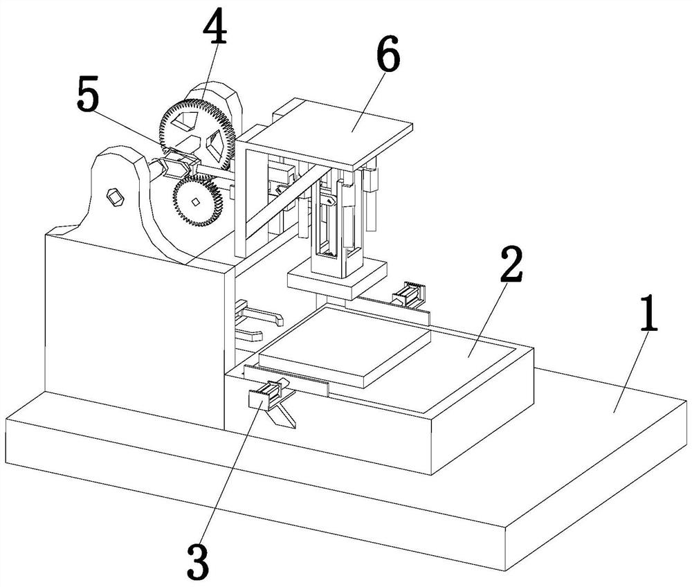
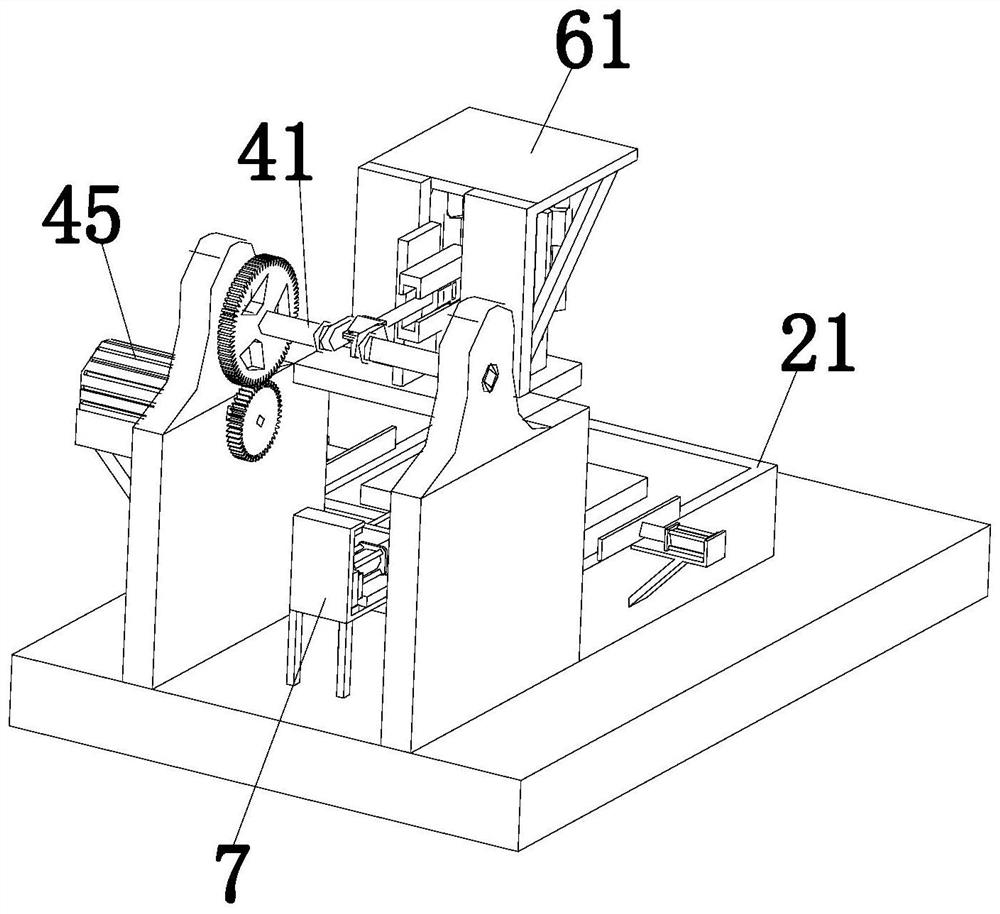
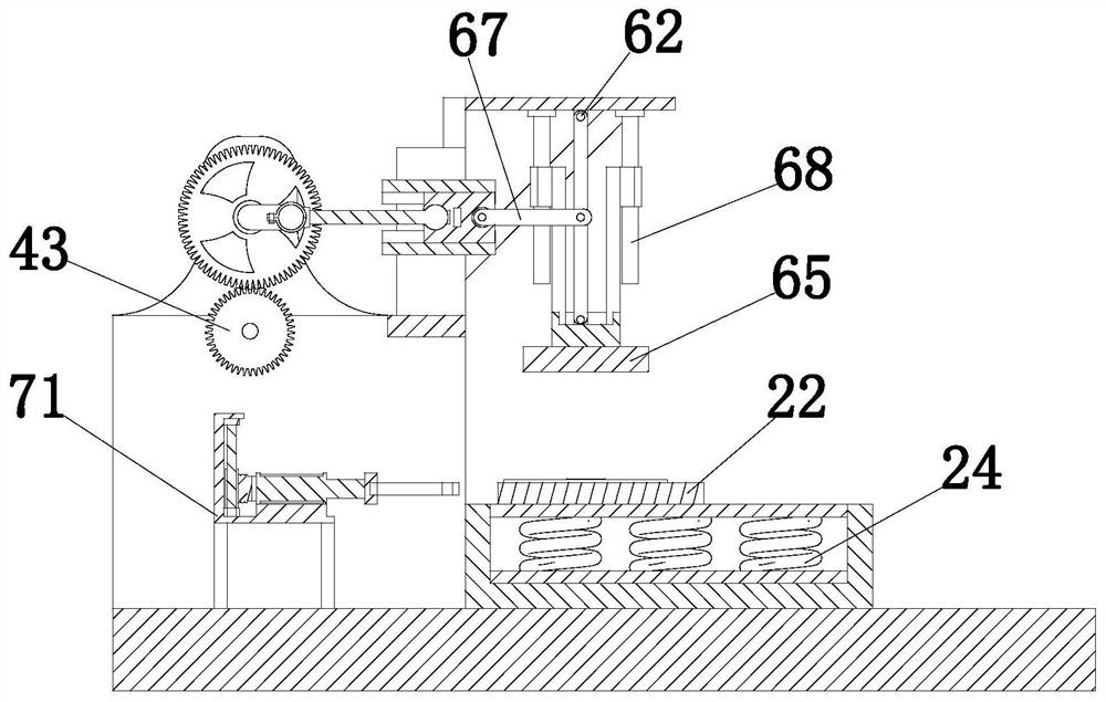
The invention relates to the technical field of machine manufacturing, in particular to a stamping device for mechanical equipment manufacturing. The stamping device comprises a bottom plate, a bufferdevice, limiting devices, a driving device, a moving device, a stamping device and an overturning device, the bottom plate is arranged on a platform, and the buffer device is arranged at the top of the bottom plate; the limiting devices are symmetrically arranged on the two side walls of the buffering device, the driving device is arranged beside the buffering device and installed on the top of the bottom plate, the moving device is arranged on the driving device, and the stamping device is arranged over the buffering device and installed on the moving device; and the overturning device is mounted at the top of the bottom plate. According to the stamping device, through mutual operation of the buffer device, the limiting devices, the driving device, the moving device, the stamping deviceand the overturning device, a stamped part can be fixed, the stamping effect on the stamped part is improved, the whole machining efficiency is improved, and the application range is wide.

Description

technical field [0001] The invention relates to the technical field of mechanical manufacturing, in particular to a stamping device used in the manufacturing of mechanical equipment. Background technique [0002] Stamping is a forming processing method that applies external force to plates, strips, pipes and profiles by presses and molds to cause plastic deformation or separation to obtain workpieces (stamping parts) of required shape and size. [0003] For example, the patent with the publication number CN209849704U relates to a stamping device for mechanical equipment manufacturing, including a mounting seat, a lower mold and an upper mold. The slider is connected to the upper end of the upper mold, the lower mold includes the main body of the lower mold, the main body of the lower mold is provided with a third mold, the left and right ends of the third mold are respectively symmetrically provided with a first mold, and the front and rear ends of the third mold are respect...

Claims


Application Information

Patent Timeline
Patent Type & Authority Applications(China)
IPC IPC(8): B21D22/02B21D43/00B21D43/10F16F15/067F16F15/02B65G47/248
CPCB21D22/02B21D43/003B21D43/105B65G47/248F16F15/02F16F15/067
Inventor 李登进
Owner 李登进
Why Eureka
Try Eureka