High-precision stamping equipment for lower rail of sliding rail

A stamping equipment, high-precision technology, applied in the field of stamping equipment, can solve the problems of inconvenient disassembly of the slide plate, debris sputtering, etc.

Pending Publication Date: 2021-08-20
JIAXING MINSHI MASCH CO LTD
View PDF1 Cites 0 Cited by
  • Summary
  • Abstract
  • Description
  • Claims
  • Application Information

AI Technical Summary

Problems solved by technology

[0006] Aiming at the deficiencies of the prior art, the present invention provides a high-precision stamping equipment for the lower rail of the slide rail, which solves the problems of debris splashing during the stamping process and inconvenient disassembly of the slide plate mentioned in the above technical background

Method used


Image

  • High-precision stamping equipment for lower rail of sliding rail
  • High-precision stamping equipment for lower rail of sliding rail
  • High-precision stamping equipment for lower rail of sliding rail

Examples


Embodiment

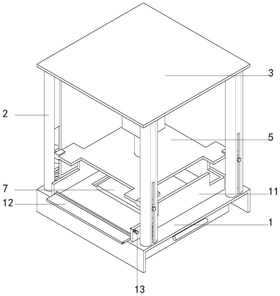
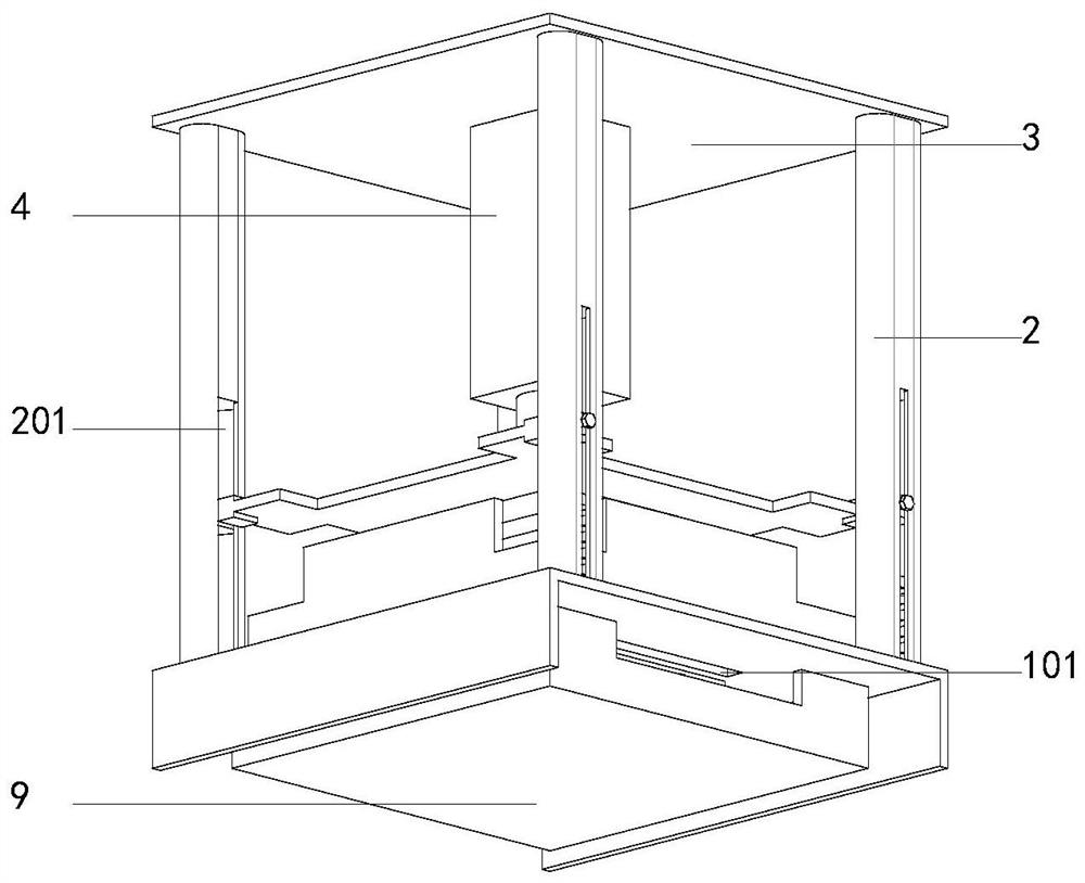
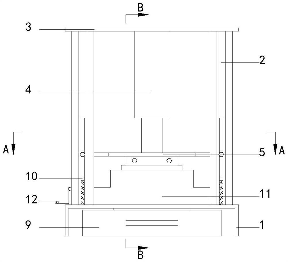
[0028] Such as figure 1 , figure 2 and image 3 As shown, a high-precision stamping equipment for the lower rail of a slide rail proposed by an embodiment of the present invention includes a base plate 1 in contact with the ground, and guide rails 2 are provided at the four corners of the upper surface of the base plate 1, and the guide rails 2 The top plate 3 is fixed on the upper end of the top plate 3, and the center position of the lower surface of the top plate 3 is provided with a hydraulic cylinder 4. The lower end of the hydraulic cylinder 4 is provided with a slide plate 5 that slides with the guide slide rail 2 in the vertical direction, and the lower end of the slide plate 5 is fixed with a stamping plate 6. The lower pressure plate 7 is embedded in the center of the upper surface of the bottom plate 1, and the upper surface of the bottom plate 1 is provided with a coaming plate 11, and the side of the gap of the coaming plate 11 is hinged with a flap 12. By setti...


PUM


Abstract

The invention belongs to the technical field of stamping equipment, and particularly relates to high-precision stamping equipment for a lower rail of a sliding rail. The high-precision stamping equipment comprises a bottom plate in contact with the ground, guide sliding rails are arranged at four corners of the upper surface of the bottom plate, a top plate is fixed to the upper ends of the guide sliding rails, a hydraulic oil cylinder is arranged in the center of the lower surface of the top plate, and sliding plates in sliding connection with the guide sliding rails in the vertical direction are arranged at the lower end of the hydraulic oil cylinder. According to the high-precision stamping equipment, a surrounding plate and a turning plate are arranged, so that the position of a part to be stamped is conveniently shielded during stamping, rusty pieces and chippings on the part are prevented from splashing to the periphery and hurting operators, the chippings generated during stamping are conveniently collected through a collecting box arranged below a through groove formed in the bottom plate, the sliding plates and sliding blocks in the guide sliding rails are fixed to the sliding plates through first bolts, so that the guide sliding rails play a role in guiding the sliding plates, and the situation that a stamping plate fixed to the sliding plates deflects during stamping, and stamping forming of parts is affected is avoided.

Description

technical field [0001] The invention relates to the technical field of stamping equipment, in particular to a high-precision stamping equipment used for the lower rail of a slide rail. Background technique [0002] Stamping equipment is a kind of special machine equipment that uses impact to press out products. It is widely used in the metal processing industry. For example, the invention patent with the Chinese application number CN200520039758.2 discloses a body structure of stamping equipment. The body is in the form of a vertical faucet. mouth open. The upper lip is equipped with a pressure cylinder installation platform, that is, the upper lip workbench, and the pressure cylinder is arranged on the platform through an adapter flange. The lower lip is provided with a lower lip workbench, which is connected to the body through a right-angled triangle support plate. On the top, the fixed module for fixing the lower mold is installed on the upper surface of the lower lip w...

Claims


Application Information

Patent Timeline
IPC IPC(8): B21D22/02B21D37/12B21D55/00B21D45/00
CPCB21D22/02B21D37/12B21D45/00B21D55/00
Inventor 杨冬刘虎杨甲瑞朱沪钢
Owner JIAXING MINSHI MASCH CO LTD
Why Eureka
Try Eureka