Protective cover with high safety performance for welding

A technology of safety performance and protective cover, applied in the field of protective cover, can solve the problems of injury, easy to cause safety accidents, blank panic of staff, etc.

Inactive Publication Date: 2021-05-18
温州宏姿机械科技有限公司
View PDF0 Cites 2 Cited by
  • Summary
  • Abstract
  • Description
  • Claims
  • Application Information

AI Technical Summary

Problems solved by technology

[0003] In the existing welding operation, in order to improve the safety during the welding process, the protective cover is generally used for safety protection. During the welding process, more sparks will be generated, and the sparks will splash onto the goggles of the protective cover. The moving speed is fast, which will cause a surprise feeling t...

Method used


Image

  • Protective cover with high safety performance for welding
  • Protective cover with high safety performance for welding
  • Protective cover with high safety performance for welding

Examples


Embodiment 1

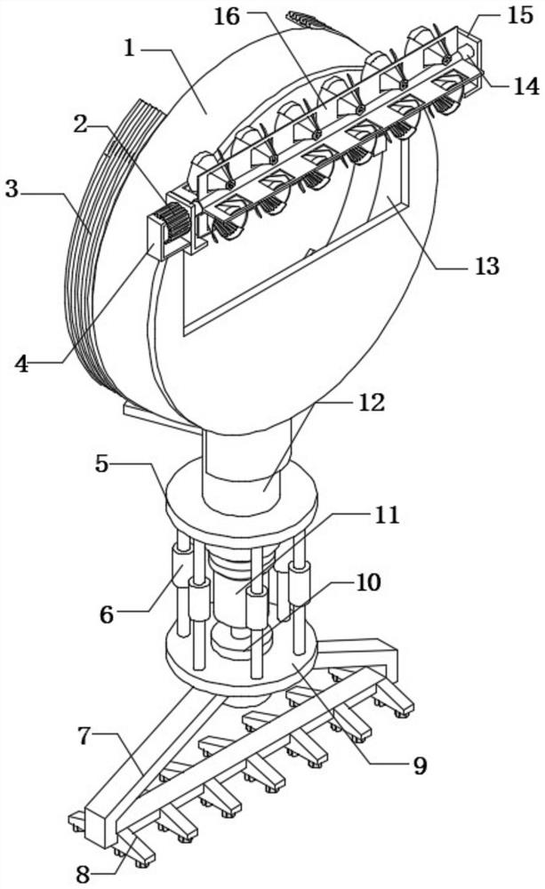
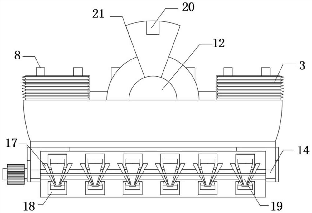
[0028] refer to Figure 1-5 , a protective cover with high safety performance for welding, comprising a protective cover body 1, the outer wall of the protective cover body 1 near the top is fixedly connected with two fixing frames 15, and the outer wall of one of the fixing frames 15 is fixedly connected with a motor plate 4, The outer wall of the motor plate 4 is fixedly connected with the motor 2, the output shaft of the motor 2 is fixedly connected with the rotating shaft 14 through a coupling, and the rotating shaft 14 is connected to the outer wall of one side of another fixed frame 15 through a bearing, and the outer wall of the rotating shaft 14 is equidistantly fixed Rotating blades 16 are connected, and the outer walls of each rotating blade 16 are provided with installation holes 18 at equal distances. The inner walls on both sides of the installation holes 18 are fixedly connected with compression plates 17, and the outer walls of the two compression plates 17 are f...

Embodiment 2

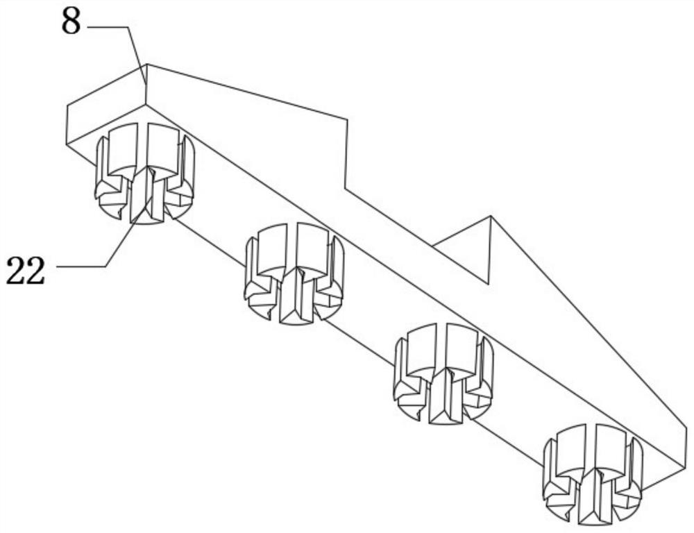
[0037] refer to Image 6 , a protective cover with high safety performance for welding, comprising a protective cover body 1, the outer wall of the protective cover body 1 near the top is fixedly connected with two fixing frames 15, and the outer wall of one of the fixing frames 15 is fixedly connected with a motor plate 4, The outer wall of the motor plate 4 is fixedly connected with the motor 2, the output shaft of the motor 2 is fixedly connected with the rotating shaft 14 through a coupling, and the rotating shaft 14 is connected to the outer wall of one side of another fixed frame 15 through a bearing, and the outer wall of the rotating shaft 14 is equidistantly fixed Rotating blades 16 are connected, and the outer walls of each rotating blade 16 are provided with installation holes 18 at equal distances. The inner walls on both sides of the installation holes 18 are fixedly connected with compression plates 17, and the outer walls of the two compression plates 17 are fixe...


PUM


Abstract

The invention belongs to the technical field of safety protection, and particularly relates to a protective cover with high safety performance for welding. The protective cover is characterized by comprising a protective cover body. By arranging a motor, a rotating shaft and rotating blades, in the welding process, a worker carries out safety protection through the protective cover body, in the welding process, the motor is started, the motor drives the rotating blades to rotate through the rotating shaft, and therefore sparks generated in the welding process are blown to other places and prevented from splashing to goggles to cause accidents, meanwhile, mounting holes are formed in the rotating blades, flow limiting plates and compression plates are mounted on the inner walls of the mounting holes, wind power is compressed and guided through the flow limiting plates and the compression plates, the wind power collection range is wider, then the wind power is discharged from shrinking through holes in connecting rings, the potential energy of the wind power is improved, and therefore the wind blowing effect is improved; and it is ensured that te sparks generated in the welding process cannot be sputtered to the protective cover body, and the protective effect of the protective cover is improved.

Description

technical field [0001] The invention relates to the technical field of safety protection, in particular to a protective cover with high safety performance for welding. Background technique [0002] Safety protection, that is, safety protection, the so-called safety means no danger, no infringement, and no accidents; the so-called protection means precautions and alerts, and precautions refer to preparations to deal with attacks or avoid victims, and alerts refer to precautions and protections; When performing welding operations, the electric sparks generated by welding are likely to cause injury to the staff. In order to avoid safety accidents, safety protection is generally carried out through protective covers. [0003] In the existing welding operation, in order to improve the safety during the welding process, the protective cover is generally used for safety protection. During the welding process, more sparks will be generated, and the sparks will splash onto the goggle...

Claims


Application Information

Patent Timeline
IPC IPC(8): B23K37/00
CPCB23K37/006
Inventor 包伦壮郑海君
Owner 温州宏姿机械科技有限公司
Why Eureka
Try Eureka