A Composite Deflection Joint Mechanism for Robot

A technology of robots and slewing mechanisms, applied in the field of robots, can solve the problems of limited mobility and flexibility of robots, and achieve the effect of shortening the length of the whole machine, increasing the stability, and simplifying the drive control system.

Active Publication Date: 2022-03-18
SHENYANG AEROSPACE UNIVERSITY
View PDF0 Cites 0 Cited by
  • Summary
  • Abstract
  • Description
  • Claims
  • Application Information

AI Technical Summary

Problems solved by technology

The joint deflection angle of this type of joint robot is limited by the width of the robot rods on both sides of the joint. Under the condition of a certain size of the robot's rotary joint, the larger the width of the rods on both sides, the smaller the deflection angle of the joint, and the robot's motion ability and flexibility are limited.
Especially the special robot structure in the special field has high requirements on the flexibility and structural size of the robot. The traditional robot deflection joint structure is difficult to meet the design requirements for improving the performance of this type of robot, such as rescue and search robots, transmission line inspection robots, etc.

Method used


Image

  • A Composite Deflection Joint Mechanism for Robot
  • A Composite Deflection Joint Mechanism for Robot
  • A Composite Deflection Joint Mechanism for Robot

Examples


Embodiment Construction

[0047] The following will clearly and completely describe the technical solutions in the embodiments of the present invention with reference to the accompanying drawings in the embodiments of the present invention. Obviously, the described embodiments are only part of the embodiments of the present invention, not all of them.

[0048]In describing the present invention, it is to be understood that the terms "upper", "lower", "left", "right", "horizontal", "top", "bottom", "inner", "outer" etc. indicate The orientation or positional relationship is based on the orientation or positional relationship shown in the drawings, and is only for the convenience of describing the present invention and simplifying the description, rather than indicating or implying that the referred device or element must have a specific orientation, be configured in a specific orientation, and operation, and therefore should not be construed as limiting the invention. In addition, the terms "a" and "two...


PUM


Abstract

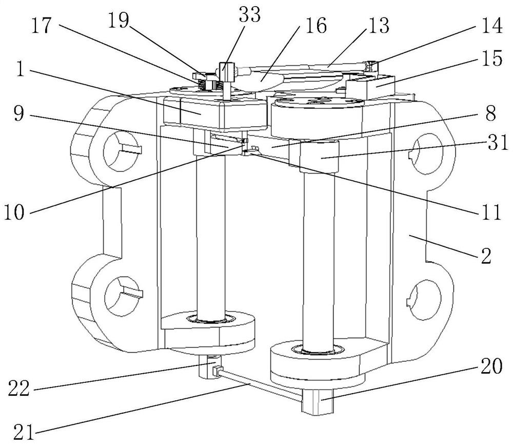
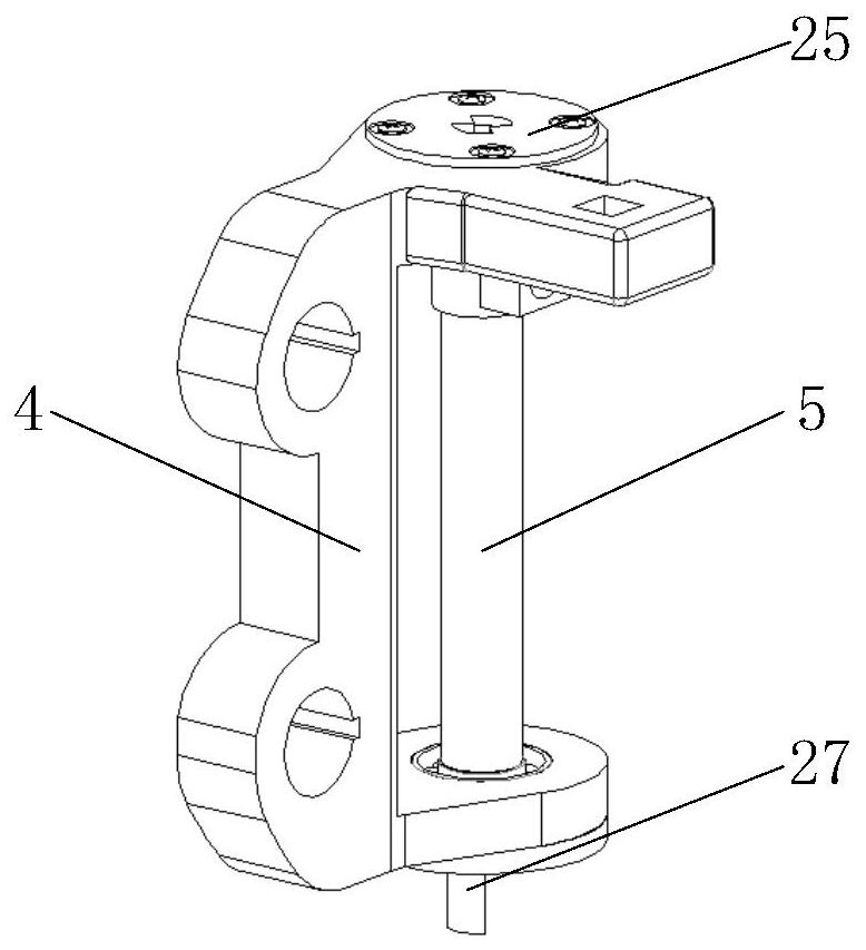
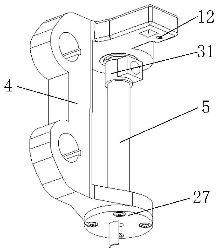
A robot compound deflection joint mechanism belongs to the technical field of robots. The composite deflection joint mechanism of the robot includes a joint one, a joint two, a cylindrical cam mechanism, a steering drive motor, a spring rod mechanism and a slewing mechanism, the joint one includes the joint external connection seat one and the joint shaft one, and the joint two includes the joint external connection seat two And joint shaft 2, the cylindrical cam mechanism includes cylindrical cam, roller push rod and landing platform, the upper motor shaft of the steering drive motor is connected with the driving rocker, the driving rocker is connected with the moving slider, and the moving slider is installed on the arc In the slideway, the lower side motor shaft of the steering drive motor is connected with the cylindrical cam, the spring bar mechanism includes a spring, a spring bar and a spring seat, and the slewing mechanism includes a rotary block, a pin connection rod and a pin connection block. The composite deflection joint mechanism of the robot can effectively adapt to various obstacles in different working environments, the stress situation is reasonable, the deflection angle is larger than that of the traditional rotary joint, and the working space is more flexible.

Description

technical field [0001] The invention relates to the technical field of robots, in particular to a robot compound deflection joint mechanism. Background technique [0002] The multi-unit serial robot configuration has good obstacle avoidance and fault tolerance capabilities, and has a wide range of applications in the fields of disaster rescue, inspection and monitoring of complex environments. Traditional tandem robot deflection joints mostly use a single rotary shaft, and the center of rotation is arranged in the symmetrical plane of the robot. The steering drive motor directly drives the rotary shaft to rotate or indirectly drives the rotary shaft to rotate through intermediate transmission mechanisms such as reducers and synchronous belts. The rotary shaft and the components on one side of the joint Fixed connection or keyed connection, hinged to the other side member. The joint deflection angle of this type of joint robot is limited by the width of the robot rods on bot...

Claims


Application Information

Patent Timeline
Patent Type & Authority Patents(China)
IPC IPC(8): B25J17/00
CPCB25J17/00
Inventor 陶广宏耿世雄何明陈淋
Owner SHENYANG AEROSPACE UNIVERSITY
Why Eureka
Try Eureka