
An auxiliary runner structure to prevent deformation of injection molded products

A technology of injection molding products and auxiliary flow, applied in the field of injection molding process equipment, can solve problems such as affecting the assembly of assembly parts, prone to distortion and unqualified size, etc., to protect bump damage, improve shrinkage deformation, and improve structural strength and rigidity Effect

Active Publication Date: 2022-02-08
DONGFENG MOTOR CORP HUBEI
View PDF13 Cites 0 Cited by
  • Summary
  • Abstract
  • Description
  • Claims
  • Application Information

AI Technical Summary

Problems solved by technology

[0002] In automobiles, some injection molded parts need to be designed in a partially disconnected state due to the influence of the overall shape. This shape design leads to poor rigidity of the product itself and is prone to distortion and deformation.
The whole process of injection molding process is: mold closing - filling - holding pressure - cooling - mold opening and picking - next cycle, in which the filling process forms 95% - 99% of the product volume, and the rest depends on The product is filled with pressure, and the shrinkage of the product after cooling is compensated by holding the pressure; the product shrinks after cooling, and the product also shrinks and deforms at the disconnection, so the size is unqualified, which in turn affects the assembly of the assembly parts; At the same time, this product also needs to be electroplated after injection molding. Electroplating products have a very important feature. The end and sharp corners of the product are easy to accumulate electroplating solution, and it is easy to be scratched after electroplating. Therefore, when designing general injection molds, it is necessary to End Design Plating Protection Corner

Method used


Image

  • An auxiliary runner structure to prevent deformation of injection molded products
  • An auxiliary runner structure to prevent deformation of injection molded products
  • An auxiliary runner structure to prevent deformation of injection molded products

Examples


Embodiment Construction

[0024] The present invention will be further described in detail below in conjunction with the accompanying drawings and specific embodiments to facilitate a clear understanding of the present invention, but they do not limit the present invention.

[0025] Some existing products have high requirements on appearance. During the injection molding process, the pressure-holding effect of the product at the end of the flow is not ideal, even if the pressure is maintained, the plastic cannot be filled to the end of the flow for feeding. How to solve the shrinkage deformation of the product at the break has become the key to the injection molding process of such parts.

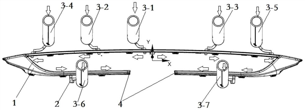
[0026] Such as figure 1 The product 1 in the prior art shown, the outer surface is the appearance surface, and the bottom is the non-appearance surface. After the injection molding production, it needs to be electroplated, and the I place is disconnected, which is the flow end of the product during injection molding...


PUM


Abstract

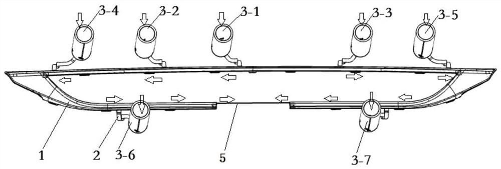
The invention discloses an auxiliary channel structure for preventing deformation of injection molded products. It includes a cavity channel for plastic melt to pass through, a main nozzle and a plurality of nozzles, the main nozzle and a plurality of nozzles communicate with the cavity channel through the gate, the main nozzle and a plurality of A control valve needle is provided in the nozzle, and an auxiliary flow channel structure is provided at the end of the disconnected plastic melt flow of the cavity channel, and the auxiliary flow channel structure is connected to the bottom of the product, and the auxiliary flow channel structure includes The first auxiliary gate, the second auxiliary gate, the third auxiliary gate, the fourth auxiliary gate and the flow channel; the first auxiliary gate and the third auxiliary gate are located at the same level, The second auxiliary gate is equal to the first auxiliary gate. The invention improves the structural strength and rigidity of the injection molding product before electroplating, and the product will not be distorted and deformed during the overall electroplating process.

Description

technical field [0001] The invention belongs to the technical field of injection molding process equipment, and in particular relates to an auxiliary flow channel structure for preventing deformation of injection molding products. Background technique [0002] In automobiles, some injection molded parts need to be designed in a partially disconnected state due to the influence of the overall shape. This shape design leads to poor rigidity of the product itself and is prone to distortion. The whole process of injection molding process is: mold closing - filling - holding pressure - cooling - mold opening and picking - next cycle, in which the filling process forms 95% - 99% of the product volume, and the rest depends on The product is filled with pressure, and the shrinkage of the product after cooling is compensated by holding the pressure; the product shrinks after cooling, and the product also shrinks and deforms at the disconnection, so the size is unqualified, which in t...

Claims


Application Information

Patent Timeline
Patent Type & Authority Patents(China)
IPC IPC(8): B29C45/27
CPCB29C45/2701B29C45/2708B29C45/2703
Inventor 肖海东张琴王贞赵延强吴阳春
Owner DONGFENG MOTOR CORP HUBEI
Learn More