Supercharge Your Innovation With Domain-Expert AI Agents!

High-temperature-resistant rapid forming injection mold

An injection mold, high-temperature-resistant technology, applied in the field of high-temperature-resistant rapid prototyping injection molds, can solve problems such as position deviation, increased difficulty of molten material injection, and loss of lower mold structure

Inactive Publication Date: 2021-05-18
朱志伟
View PDF0 Cites 1 Cited by
  • Summary
  • Abstract
  • Description
  • Claims
  • Application Information

AI Technical Summary

Problems solved by technology

[0003] When the injection mold is closing the film, the movable upper mold generally presses and contacts the fixed lower mold to form an injection cavity. When the existing upper film is pressed and moved, although it already has a guiding structure, according to the injection molding of the mold Depending on the type and model, there may still be position shifts and leakage after the film is combined, and the pressing force of the lower film will be exerted on the upper film for a long time, resulting in loss of the lower die structure, reducing the service life of the components, and reducing the cost of the joint. The precision of film injection molding; when the injection molding molten material is feeding, it is easy to generate a large number of heat sources in the channel, which will generate extremely high temperature on the wrapped and sealed wall surface. If the heat-resistant structure here is insufficient, it will cause the pipe wall to crack. The molten material overflows, increasing the difficulty and inconvenience of injection molding work, and the injection port of the device is prone to rapid loss of heat source due to the necessary exhaust structure, causing the molten material to solidify in the guide tube of the molten material, which cannot be used normally. Circulation, further increases the difficulty of injection molding of molten materials, reduces the injection molding effect and pass rate of the mold; when the device drives the parts to move, it is easy to shake the moving structure, resulting in increased vibration of the combination of the upper film and the lower mold, which in turn makes the subject The damage increases, and when the injection molding melt is conveyed, it may generate a certain amount of noise, which reduces the protection of the injection molding structure

Method used


Image

  • High-temperature-resistant rapid forming injection mold
  • High-temperature-resistant rapid forming injection mold
  • High-temperature-resistant rapid forming injection mold

Examples


Embodiment 1

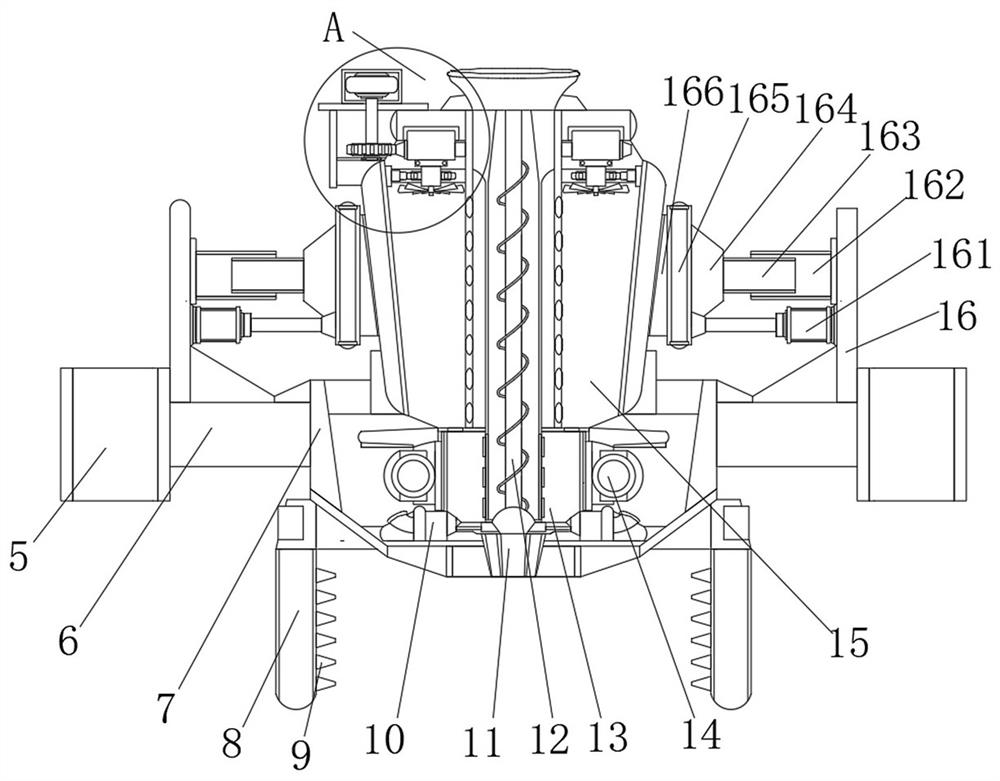
[0043] Example 1, such as image 3 and Figure 6 As shown, when the upper mold base 7 moves as a whole, the electric cylinder 161 can be activated through the console 4 to drive the installation plate 164 to approach inward under the guidance of the outer sleeve 162 and the inner sleeve 163, so that the installation plate 164 drives the sound-absorbing panel 165 The rock wool sleeve 15 is fitted and clamped with the semi-arc clamping wall 166, which not only provides a fitting and fixing effect on the outer wall of the rock wool sleeve 15, but also absorbs the impact and noise received by the rock wool sleeve 15, and passes through the semi-arc The shape of the clamping wall 166 is used for buffering and shock absorption, and the scattered fit of the sound-absorbing plate 165 and the sound-absorbing hole 167 is used to disperse and eliminate the noise, thereby increasing the functionality of the device.

Embodiment 2

[0044] Example 2, such as image 3 and Figure 4 As shown, when the molten material is guided from the injection molding tube 12, the heat source is infiltrated into the rock wool casing 15 through the injection molding tube 12, and the drive motor 221 is used to start the drive motor 221 to drive the gear B223 to rotate through the injection molding tube 12, so that the gear B223 drives the meshing The outer ring gear 224 of the outer ring gear 224 makes the slider 222 rotate in a ring under the rotation of the annular chute 22. With the rotation of the slider 222, the rotating rod 227 and the gear C226 are forced to rotate under the meshing fit with the inner ring gear 225. The rod 227 drives the fan blade 228 to rotate to form a guide wind, and the heat source in the infiltration and rock wool sleeve 15 flows downward, so that the heat source is guided from the annular guide flow groove 23 to the heat insulation cavity while dissipating heat from the injection tube 12 13, ...


PUM


Abstract

The invention discloses a high-temperature-resistant rapid forming injection mold which comprises a base, sleeve columns are arranged on the two sides of the top of the base, guide sleeves matched with each other are arranged on the outer sides of the two sets of the sleeve columns, a lower mold base is arranged in the middle of the top of the base, and guide pipes are arranged on the two sides of the interior of the lower mold base. A gear A is arranged on the side, close to the guide pipes, of the top of the interior of the lower mold base, telescopic rods are symmetrically arranged in the middle of the bottom of the lower mold base, and injection mold bases connected with each other are arranged on the tops of the two sets of the telescopic rods. Through mutual correspondence of an upper mold base and the injection mold base, the upper mold base can descend to drive a sleeve rod, a rack A, the guide pipes, the gear A and a rack B to generate linkage fit, so that the upper mold base in the descending process is in mutual corresponding contact with the injection mold base which is in linkage with parts for lifting. According to the mold combining structure, mold combining work is done through upper and lower two-group linkage type splicing, and the mold combining precision and efficiency are greatly improved.

Description

technical field [0001] The invention relates to the technical field of injection molds, in particular to a high temperature resistant rapid prototyping injection mold. Background technique [0002] Injection molding is a tool for producing plastic products, and it is also a tool for giving plastic products a complete structure and precise dimensions. Injection molding is a processing method used in the mass production of certain complex-shaped parts. Specifically, it refers to melting plastic by heat. The injection molding machine injects into the mold cavity under high pressure, and after cooling and solidifying, the molded product is obtained. [0003] When the injection mold is closing the film, the movable upper mold generally presses and contacts the fixed lower mold to form an injection cavity. When the existing upper film is pressed and moved, although it already has a guiding structure, according to the injection molding of the mold Depending on the type and model, ...

Claims


Application Information

Patent Timeline
Patent Type & Authority Applications(China)
IPC IPC(8): B29C45/66B29C45/26B29C45/78
CPCB29C45/2602B29C45/66B29C45/78
Inventor 朱志伟
Owner 朱志伟
Features
  • R&D
  • Intellectual Property
  • Life Sciences
  • Materials
  • Tech Scout
  • Unparalleled Data Quality
  • Higher Quality Content
  • 60% Fewer Hallucinations
Learn More