
Box filling machine for cross rods of ring lock scaffold

A boxing machine and scaffolding technology, which is applied in the field of cross-bar boxing machines for buckle scaffolding, can solve the problems of being unable to reach the robot, the robot cannot hoist the cross-bar, and the efficiency of conveying and boxing is low.

Pending Publication Date: 2021-05-18
付尤东 +2
View PDF0 Cites 1 Cited by
  • Summary
  • Abstract
  • Description
  • Claims
  • Application Information

AI Technical Summary

Problems solved by technology

[0004] However, when the crossbar is pushed to the frame preset station outside the guide rail terminal by the toothed conveyor belt, the direction of the movable lock at the end of the crossbar is in a vertical state, while the existing crossbar boxing system requires that the end of the crossbar The active locks cannot be in a vertical state, and need to be rotated and stacked
Therefore, the existing cross-bar box packing machine for scaffolding with buckles cannot meet the requirements of the robot for stacking the cross-bars. The robot cannot lift the cross-bars or needs to be re-stacked manually, and the efficiency of transportation and packing is low.

Method used


Image

  • Box filling machine for cross rods of ring lock scaffold
  • Box filling machine for cross rods of ring lock scaffold
  • Box filling machine for cross rods of ring lock scaffold

Examples


Embodiment Construction

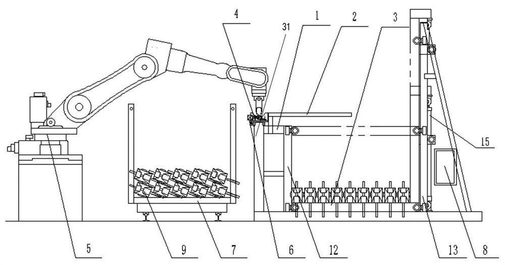
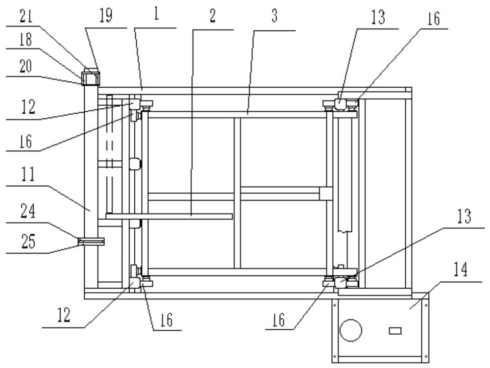
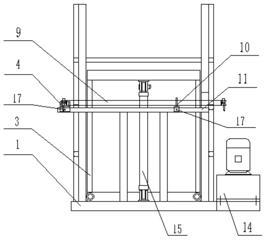
[0024] Pan buckle scaffolding cross bar boxing machine, the left end of the frame 1 has a vertical rod, the top of which is connected with the slide rail 11, there are two first guide rails 12, two second guide rails 13 on the base of the frame 1, and a lifting box 3 The right end of the platform is connected with two columns 33, the cross-section of the first and second guide rails is rectangular, the left corner of the platform has the first and second retaining wheels 16 to slide and cooperate with the two sides of the first guide rail 12 respectively, the right corner of the platform The 3rd, 4, 5 retaining wheels 16 are respectively slidably matched with the three sides of the 2nd guide rail 13, and the middle part of the column 33 has the 6th, 7 retaining wheels 16 respectively slidably engaged with the two sides of the 2nd guide rail 13, connecting two In the middle of the crossbeam at the upper end of the column 33, there is an upper support 29 hinged with the upper end...


PUM


Abstract

The invention relates to a box filling machine for cross rods of a ring lock scaffold, and aims to solve the problem that the cross rods cannot be hoisted by a robot or need to be manually stacked again, and consequently the conveying and box filling efficiency is low. According to the box filling machine, the left end of a rack is connected with a sliding rail, two first guide rails and two second guide rails are arranged on a base of the rack, the right end of a platform of a lifting box is connected with two stand columns, a first catch wheel and a second catch wheel are arranged at the left corner of the platform and are in sliding fit with two side faces of the first guide rails respectively, a third catch wheel, a fourth catch wheel and a fifth catch wheel are arranged at the right corner of the platform and are in sliding fit with three side faces of the second guide rails respectively, a sixth catch wheel and a seventh catch wheel are arranged in the middle of the stand columns and are in sliding fit with two side faces of the second guide rails respectively, an upper support and a lower support are hinged to the upper end and the lower end of an oil cylinder, an orientation device is arranged at one end of the sliding rail, a positioning supporting device is arranged on the sliding rail, and an included angle formed by an inclined plane, formed by the upper ends of a first directional support plate and a second directional support plate, and the horizontal plane is consistent with the state of a movable locking piece at the end of each cross rod required by a cross rod box filling system.

Description

technical field [0001] The present invention is related to the cross-bar case packing machine for the buckle scaffolding. Background technique [0002] Existing cross-bar boxing machine for coiled scaffolding includes robot, workpiece box and cross-bar conveying device, cross-bar conveying device includes frame and transmission device, above the frame there are several longitudinal support bars located on the same plane or / and On the inclined plane, there are symmetrical guide supports on the frame on both sides of the plane to connect with the guide rails. The transmission device includes a motor, and the driving wheel on the power output shaft of the motor passes through the first driven wheel on the first driven shaft on the frame. Transmission belt transmission connection, the second and third driven wheels on the first driven shaft on the frame are respectively connected with the fourth and fifth driven wheels on the second driven shaft on the frame through a toothed co...

Claims


Application Information

Patent Timeline
Patent Type & Authority Applications(China)
IPC IPC(8): B65B35/50B65B35/56
CPCB65B35/50B65B35/56
Inventor 付尤东张邦惠周彤
Owner 付尤东
Learn More