Concrete frame column roll welding spiral stirrup reinforcement cage and preparation method thereof

A technology of spiral stirrups and steel cages, which is applied in the directions of columns, piers, pillars, etc., can solve the problem that multi-layer composite spiral stirrups do not provide solutions.

Pending Publication Date: 2021-05-18
JILIN JIANZHU UNIVERSITY
View PDF1 Cites 0 Cited by
  • Summary
  • Abstract
  • Description
  • Claims
  • Application Information

AI Technical Summary

Problems solved by technology

However, the utility model patent only solves the seam welding of one layer of spiral stirrups, and does not provide a solution when multi-layer composite spiral stirrups are required

Method used


Image

  • Concrete frame column roll welding spiral stirrup reinforcement cage and preparation method thereof
  • Concrete frame column roll welding spiral stirrup reinforcement cage and preparation method thereof
  • Concrete frame column roll welding spiral stirrup reinforcement cage and preparation method thereof

Examples


Embodiment Construction

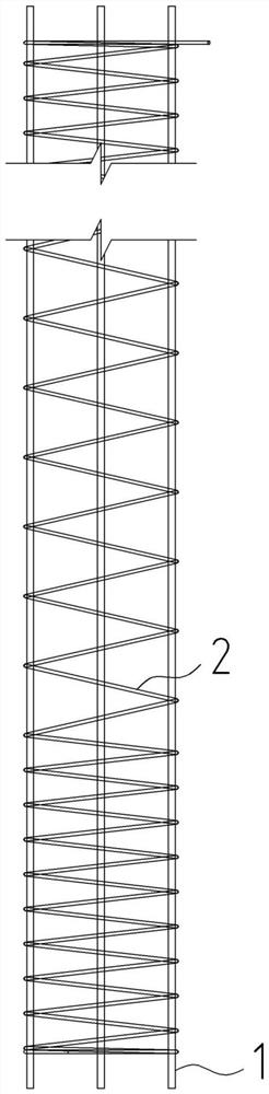
[0044] A concrete frame column roll welded spiral stirrup reinforcement cage, such as Figure 1 to Figure 9 As shown, the column roll welded spiral stirrup reinforcement cage 7 includes an inner ring longitudinal reinforcement 1, an inner ring polygonal spiral stirrup 2, a middle longitudinal reinforcement 3, a middle polygonal spiral stirrup 4, an outer ring longitudinal reinforcement 5 and an outer ring polygonal spiral stirrup Tendon 6;

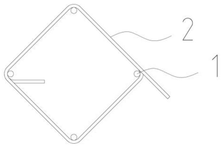
[0045] Such as figure 2 and image 3 As shown, the inner ring longitudinal steel bar 1 is at the inner side of the corner of the inner ring polygonal spiral stirrup 2, and the inner ring polygonal spiral stirrup 2 is wound around the outer side of the inner ring longitudinal steel bar 1 and bent at the position of the inner ring longitudinal steel bar 1;

[0046] Such as Figure 5 and Figure 6 As shown, the middle longitudinal steel bar 3 is at the inner side of the corner of the middle polygonal spiral stirrup 4, and the middle poly...


PUM


Abstract

The invention provides a concrete frame column roll welding spiral stirrup reinforcement cage and a preparation method thereof, and belongs to the technical field of civil engineering. The concrete frame column roll welding spiral stirrup reinforcement cage comprises inner ring longitudinal reinforcements, inner ring polygonal spiral stirrups, middle longitudinal reinforcements, middle polygonal spiral stirrups, outer ring longitudinal reinforcements and outer ring polygonal spiral stirrups. The concrete frame column roll welding spiral stirrup reinforcement cage is roll-welded in a spot welding mode, so that the production efficiency of the concrete frame column reinforcement cage is improved, the labor amount is reduced, the steel consumption is reduced, and the building construction cost is reduced.

Description

technical field [0001] The invention belongs to the technical field of civil engineering and relates to the design and construction of a concrete frame structure, in particular to a concrete frame column rolling-welded spiral stirrup reinforcement cage and a preparation method thereof. Background technique [0002] For the stirrups of concrete frame columns, the method of binding ordinary stirrups specified in the "Code for Design of Concrete Structures" GB50010-2010 (2015 Edition) is used in most cases at present. Consumption of labor, the first paragraph of Article 11.4.17 stipulates that when using spiral hoops, composite or continuous composite rectangular spiral hoops, the volume reinforcement ratio of the hoops in the column hoop density area can be reduced by about 20%, and the use of Spiral hoops, composite or continuous composite rectangular spiral hoops can also save about 10% of the steel consumption of common stirrup hooks, which can save 30% of steel, reduce eng...

Claims


Application Information

Patent Timeline
Patent Type & Authority Applications(China)
IPC IPC(8): E04C5/06E04C3/34B21F27/20B21F27/10
CPCB21F27/10B21F27/20E04C3/34E04C5/0609E04C5/0618
Inventor 孟凡林沙丽荣孟祥瑞桑思宇李建科李兆杰殷承诺梁媛
Owner JILIN JIANZHU UNIVERSITY
Why Eureka
Try Eureka