
Automobile side sliding door guide rail and electric side sliding door system thereof

A car side and guide rail technology, applied to doors, vehicle maintenance, vehicle parts, etc., can solve problems such as unstable connection of hinge rollers, inappropriateness, shaking, etc.

Pending Publication Date: 2021-05-18
JIANGSU CHANG NING ET LTD
View PDF10 Cites 0 Cited by
  • Summary
  • Abstract
  • Description
  • Claims
  • Application Information

AI Technical Summary

Problems solved by technology

[0004] But the above-mentioned automobile side sliding door guide rail also has the following defects in use: 1. Although the guide rail can make the side sliding door open, the hinge rollers will not come off from the guide rail, preventing the side sliding door from falling off from the vehicle body, but During the use of the guide rail, the hinge rollers of the side sliding door will directly contact with the side wall of the guide rail, resulting in greater friction. Shaking occurs during the opening and closing process; 2. Although the guide rail is not easy to cause the side sliding door hinge rollers to fall off from the guide rail during use, it cannot allow the side sliding door to be better cushioned when opening and closing, which makes the side sliding door If the kinetic energy is too large when the sliding door is opened, it will cause rebound, which will not only cause damage to the guide rail, but also have a certain impact on the door, which is very inappropriate.

Method used


Image

  • Automobile side sliding door guide rail and electric side sliding door system thereof
  • Automobile side sliding door guide rail and electric side sliding door system thereof
  • Automobile side sliding door guide rail and electric side sliding door system thereof

Examples


Embodiment Construction

[0031] The following will clearly and completely describe the technical solutions in the embodiments of the present invention with reference to the accompanying drawings in the embodiments of the present invention. Obviously, the described embodiments are only some, not all, embodiments of the present invention. Based on the embodiments of the present invention, all other embodiments obtained by persons of ordinary skill in the art without making creative efforts belong to the protection scope of the present invention.

[0032] see Figure 1 to Figure 9 , the present invention provides a technical solution:

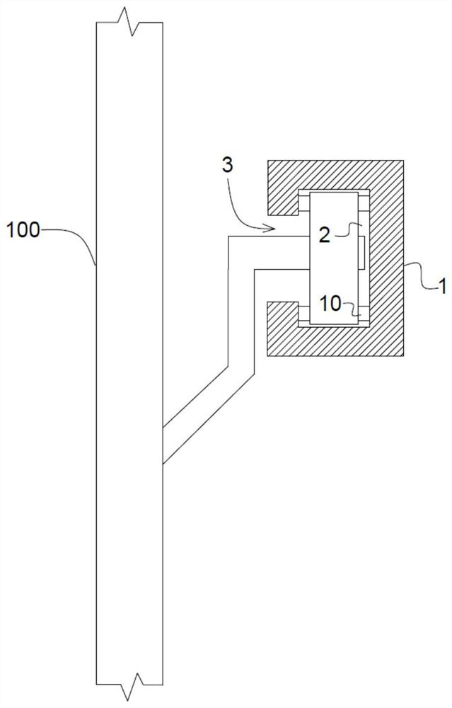
[0033] An automobile side sliding door guide rail and its electric side sliding door system, comprising a guide rail plate 1, a chute 2 for the movement of the hinge rollers of the automobile side sliding door is opened inside the guide rail plate 1, and the guide rail plate 1 is located on one side of the chute 2 There is a guide rail opening 3 on the side for the movem...


PUM


Abstract

The invention provides an automobile side sliding door guide rail and an electric side sliding door system thereof. The automobile side sliding door guide rail comprises a guide rail plate, wherein a sliding groove is formed in the guide rail plate, a guide rail opening is formed in the side, located in the sliding groove, of the guide rail plate, and buffer boxes are fixedly connected to the two ends of the guide rail plate; and a plurality of step grooves are formed in the inner wall of the sliding groove, first reset springs are arranged at the bottoms of the step grooves, connecting blocks are fixedly connected to the ends, away from the bottoms of the step grooves, of the first reset springs, connecting arms are fixedly connected to the connecting blocks, first rotating shafts are fixedly connected to the connecting arms, and rolling wheels are rotationally connected to the first rotating shafts. In the using process, a side sliding door is opened quite smoothly, clamping stagnation and springback cannot be caused, and a good buffer effect can be achieved; and the hinge rolling wheels in the guide rail can be cleaned, the situation that the automobile side sliding door is difficult to open under the condition of long-time use cannot happen, and the automobile side sliding door guide rail and the electric side sliding door system thereof are quite worthy of popularization.

Description

technical field [0001] The invention relates to the technical field of automobile side sliding doors, in particular to an automobile side sliding door guide rail and an electric side sliding door system thereof. Background technique [0002] Existing automobile doors often adopt fan-type doors hinged by hinges, and the distance between parking spaces is generally small nowadays, but fan-type doors require a large space when opening the door during use, which often causes two car doors. The fact that the side space is small and the door cannot be opened normally highlights the inconvenience of using the fan door, which leads to an increasing demand for the use of side sliding doors for car doors. The biggest advantage of side sliding doors is that they are relatively more convenient after opening. , It is convenient for passengers to enter and exit the compartment, and it is convenient for loading and unloading goods in the compartment. In order to ensure that the side slidin...

Claims


Application Information

Patent Timeline
IPC IPC(8): E05D13/00E05F5/06E05F5/08E05F15/655B60S1/62B60J5/06
CPCE05D13/00E05F15/655E05F5/08E05F5/06B60J5/06B60S1/62
Inventor 余甜李徳云舒胜璟侯志权
Owner JIANGSU CHANG NING ET LTD
Learn More