
Angle limiting force value transmission device with protection function

A technology of protection function and transmission device, applied in the direction of transmission device, belt/chain/gear, mechanical equipment, etc., can solve the problems of secondary damage, unobservable belt, eccentric wear of tensioning mechanism, etc.

Pending Publication Date: 2021-05-18
LOVOL HEAVY IND CO LTD
View PDF0 Cites 0 Cited by
  • Summary
  • Abstract
  • Description
  • Claims
  • Application Information

AI Technical Summary

Problems solved by technology

The belt drive in the transmission structure, in the actual operation process, due to problems such as deformation of the support shaft and falling off of bearing balls, the pitch surface of the drive belt will be inclined
The existing transmission belt tensioning mechanism can only be adjusted along the tensioning direction, and the adjustment of the tensioning mechanism cannot protect the inclined operation of the belt. If the tensioning surface is inclined, it will directly cause partial wear of the tensioning mechanism, and in severe cases, it will run inclined The belt may drive the inclined pulley to fly out, causing secondary damage; moreover, the inclined operation of the belt is often not easy to detect, and the operator needs to smell the peculiar smell and hear the abnormal noise before performing maintenance. At this time, the belt has basically failed, and even cause serious accident

Method used


Image

  • Angle limiting force value transmission device with protection function
  • Angle limiting force value transmission device with protection function
  • Angle limiting force value transmission device with protection function

Examples


Embodiment 1

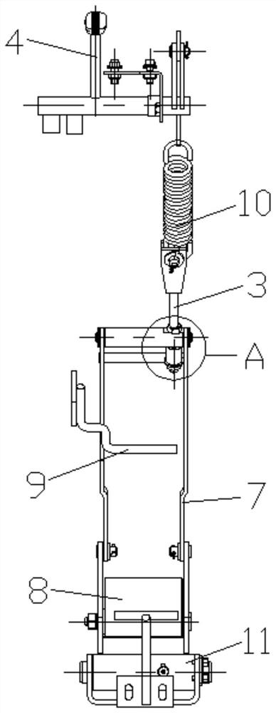
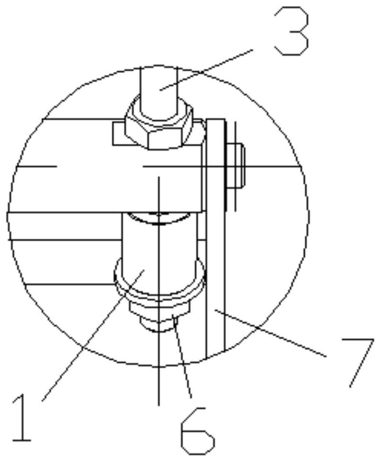
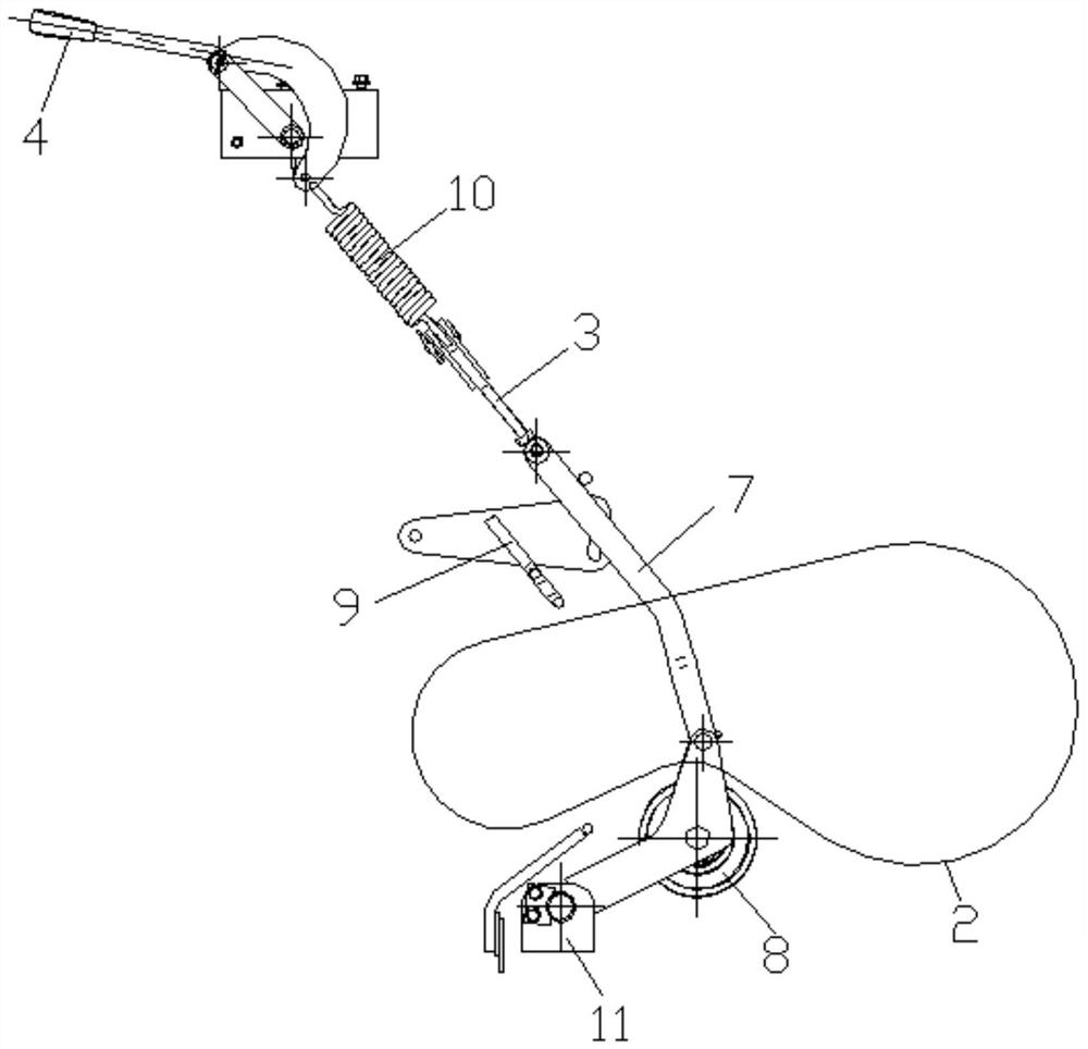
[0039] On the basis of the above structure, in this embodiment, the protective member 1 is a protective tube with both ends open. The protective tube is coaxially slidably sleeved on the lower end of the pull rod 3. The structure is simple and the design is reasonable. The protective tube and the pull rod 3 When the tension surface of belt 1 is tilted, the protective tube will break to release the tension mechanism, so that belt 1 can return to the state where the tension surface is parallel to protect belt 2.

Embodiment 2

[0041] On the basis of Embodiment 1, in this embodiment, at least one end of the protective tube is provided with at least one pre-slit 5 , which has a simple structure and reasonable design, so that the protective tube is easy to break when twisted, thereby better protecting the belt 2 .

Embodiment 3

[0043] On the basis of Embodiment 2, preferably, in this embodiment, the two ends of the protection tube are respectively provided with pre-slits 5, and the two pre-slits 5 are arranged opposite to each other, so that the protection tube is easier to break and can better protect the belt. 2.

[0044] In addition to the above-mentioned embodiments, one or more pre-slits 5 can also be set at any one end of the protection tube, for example, only one pre-slit 5 can be set at any one end of the protection tube, or two can also be set at any one end of the protection tube. Even a plurality of pre-slits 5, when the number of pre-slits 5 is two, preferably oppositely arranged, so as to facilitate rapid rupture of the protective tube; at the same time, multiple pre-slits 5 can also be set at both ends of the protective tube, and the two ends of the protective tube The number of the pre-slits 5 at the end can be the same or different, and when they are the same, they are preferably arra...


PUM


Abstract

The invention relates to an angle limiting force value transmission device with a protection function. The angle limiting force value transmission device comprises a protection piece and a tensioning mechanism for tensioning a belt, the tensioning mechanism can turn over up and down, the upper end of the tensioning mechanism is slidably connected with the lower end of a pull rod, the protection piece slidably sleeves the lower end of the pull rod, the two ends of the protection piece abut against the upper end of the tensioning mechanism and the lower end of the pull rod respectively, and when the belt inclines, the protection piece is twisted and broken to enable the disconnected state of the belt to be recovered. The angle limiting force value transmission device has the beneficial effects that tensioning adjustment of the belt can be achieved, the running state of the belt is guaranteed, meanwhile, the belt can be prevented from inclining, secondary damage caused by the fact that a belt pulley flies out is avoided, and safety and reliability are achieved.

Description

technical field [0001] The invention relates to the technical field of transmission mechanisms, in particular to an angle-limiting force value transmission device with a protection function. Background technique [0002] The tensioning part in the transmission mechanism generally needs tensioning rods and cushioning springs. Belt transmission in the transmission structure, in the actual operation process, due to problems such as deformation of the support shaft and falling off of bearing balls, the pitch surface of the transmission belt will be inclined. The existing transmission belt tensioning mechanism can only be adjusted along the tensioning direction, and the adjustment of the tensioning mechanism cannot protect the inclined operation of the belt. If the tensioning surface is inclined, it will directly cause partial wear of the tensioning mechanism, and in severe cases, it will run inclined The belt may drive the inclined pulley to fly out, causing secondary damage; m...

Claims


Application Information

Patent Timeline
Patent Type & Authority Applications(China)
IPC IPC(8): F16H7/08
CPCF16H7/08F16H7/0829F16H2007/0802F16H2007/0808
Inventor 施文龙冷峻周麒龙刘静刘成堂王俊力马进龙
Owner LOVOL HEAVY IND CO LTD
Learn More