Solar LED factory building illuminating lamp

A lighting and solar energy technology, applied in the field of lighting, can solve problems such as labor and affecting the lighting effect of lighting

Inactive Publication Date: 2021-05-18
李艳明
View PDF0 Cites 0 Cited by
  • Summary
  • Abstract
  • Description
  • Claims
  • Application Information

AI Technical Summary

Problems solved by technology

[0003] A large amount of dust is likely to be generated in the factory building during production. After the lighting lamp is used for a period of time, the surface of the bulb is easily covered with a layer of dust. People need to clean the dust on the surface regularly, otherwise it

Method used


Image

  • Solar LED factory building illuminating lamp
  • Solar LED factory building illuminating lamp
  • Solar LED factory building illuminating lamp

Examples


Embodiment 1

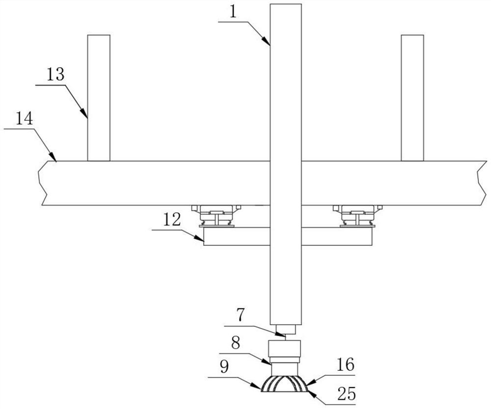
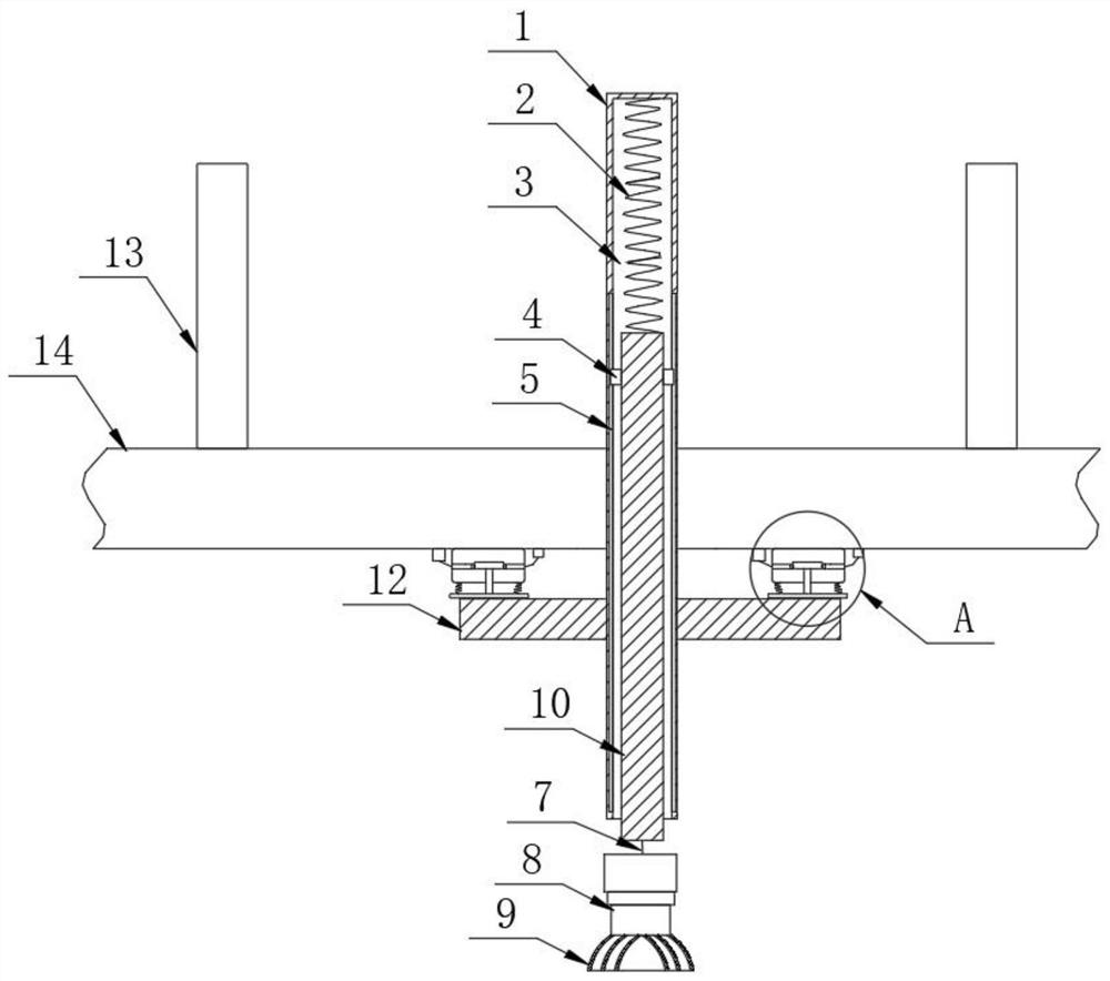
[0032] Such as Figure 1-3 As shown, the solar LED factory building lighting includes a horizontal board 14, and the two sides of the top of the horizontal board 14 are respectively provided with support rods 13. 1. It is characterized in that the bottom surface of the mounting plate 1 is longitudinally provided with a groove 3, the top surface of the groove 3 is fixedly provided with a spring 2, the bottom of the spring 2 is fixedly connected with the movable plate 10, and the two sides of the movable plate 10 are respectively fixedly arranged with Slider 4, two sliders 4 are arranged in two chute 5 respectively, and two chute 5 are set up on both sides in the groove 3 respectively, slider 4 and chute 5 are slidably matched, by being provided with slider 4 and chute 5, so that the movable plate can move up and down stably in the groove, the bottom of the movable plate 10 is connected to the lighting lamp by the chain 7, the chain 7 is made of stainless steel, and the lighting...

Embodiment 2

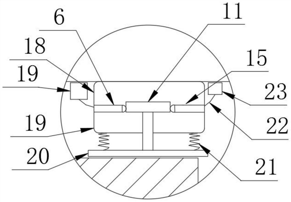
[0037] Such as Figure 1-4As shown, the solar LED factory building lighting includes a horizontal board 14, and the two sides of the top of the horizontal board 14 are respectively provided with support rods 13. 1. It is characterized in that the bottom surface of the mounting plate 1 is longitudinally provided with a groove 3, the top surface of the groove 3 is fixedly provided with a spring 2, the bottom of the spring 2 is fixedly connected with the movable plate 10, and the two sides of the movable plate 10 are respectively fixedly arranged with Slider 4, two sliders 4 are arranged in two chute 5 respectively, and two chute 5 are set up on both sides in the groove 3 respectively, slider 4 and chute 5 are slidably matched, by being provided with slider 4 and chute 5, so that the movable plate can move up and down stably in the groove, the bottom of the movable plate 10 is connected to the lighting lamp by the chain 7, the chain 7 is made of stainless steel, and the lighting ...


PUM


Abstract

The invention provides a solar light-emitting diode factory building illuminating lamp and relates to the technical field of illuminating lamps. The illuminating lamp comprises a transverse plate, supporting rods are respectively arranged on two sides of the top of the transverse plate, the transverse plate is fixed on the inner top of a factory building through the supporting rods, and a mounting plate is longitudinally arranged on the front face of the transverse plate. The illuminating lamp is characterized in that a groove is longitudinally arranged in the bottom face of the mounting plate, a first spring is fixedly arranged on the inner top face of the groove, a movable plate is fixedly connected to the bottom of the first spring, sliding blocks are fixedly arranged on the two sides of the movable plate respectively, the two sliding blocks are arranged in two sliding grooves respectively, the two sliding grooves are formed in the two sides in the groove respectively, and the sliding blocks are in sliding fit with the sliding grooves. The bottom of the movable plate is connected with an illuminating lamp through a chain, and the illuminating lamp is located below the mounting plate. The invention aims to solve the problems that an existing workshop lighting lamp is installed at a certain height, when people want to clean dust on the lighting lamp, people need to stand on a platform to look up the lighting lamp to clean the dust, and the operation is very inconvenient.

Description

technical field [0001] The invention belongs to the technical field of illuminating lamps, in particular to solar LED factory building illuminating lamps. Background technique [0002] The factory lighting refers to the lighting installed on the high place of the building in the factory area to illuminate the relatively open area, also known as the floodlight, and the projection using solar energy is also called the solar floodlight. At present, the principle of solar flood lights is that sunlight is the energy source. During the daytime, the solar panel absorbs the sun and converts it into electricity to charge the battery. At night, the electricity in the battery is used to supply power to the light source. The pipeline laying can be designed and adjusted arbitrarily, which is safe, energy-saving and pollution-free, stable and reliable without manual operation, saving electricity and maintenance-free. [0003] A large amount of dust is likely to be generated in the factor...

Claims


Application Information

Patent Timeline
IPC IPC(8): F21S9/03F21V17/16F21V21/34F21V29/74F21V29/83F21V33/00G08B21/18F21Y115/10
CPCF21S9/035F21V17/16F21V21/34F21V33/00F21V29/74F21V29/83F21Y2115/10G08B21/18Y02B10/10
Inventor 李艳明
Owner 李艳明
Why Eureka
Try Eureka