Supercharge Your Innovation With Domain-Expert AI Agents!

Automatically adjustable heat dissipation device for air purifier

An air purifier and cooling device technology, applied in the field of air purification, can solve problems such as inability to dissipate heat in time, fan speed cannot be adjusted, and machine damage

Inactive Publication Date: 2021-05-18
成都应晴白商贸有限公司
View PDF3 Cites 1 Cited by
  • Summary
  • Abstract
  • Description
  • Claims
  • Application Information

AI Technical Summary

Problems solved by technology

After working for a long time, the air purifier will generate a lot of heat inside, so it needs to be dissipated. Existing equipment generally uses fans to dissipate heat, but the fan speed cannot be adjusted, which will cause discomfort when the temperature is not high. Necessary energy waste, and will cause unnecessary wear and tear on the parts, shorten the service life, and cannot dissipate heat in time when the temperature is too high, which will cause the electronic components inside the machine to heat up, affect its stable operation, and even cause damage to the machine, so The cooling effect is not ideal
[0003] Aiming at the deficiencies of the prior art, the present invention provides an automatically adjustable heat sink for air purifiers, which has the advantages of automatically adjusting the fan speed according to the temperature, avoiding energy waste, and improving heat dissipation efficiency, and solves the problem of insufficient heat dissipation of general heat sinks. ideal question

Method used


Image

  • Automatically adjustable heat dissipation device for air purifier
  • Automatically adjustable heat dissipation device for air purifier
  • Automatically adjustable heat dissipation device for air purifier

Examples


Embodiment Construction

[0022] The following will clearly and completely describe the technical solutions in the embodiments of the present invention with reference to the accompanying drawings in the embodiments of the present invention. Obviously, the described embodiments are only some, not all, embodiments of the present invention. Based on the embodiments of the present invention, all other embodiments obtained by persons of ordinary skill in the art without making creative efforts belong to the protection scope of the present invention.

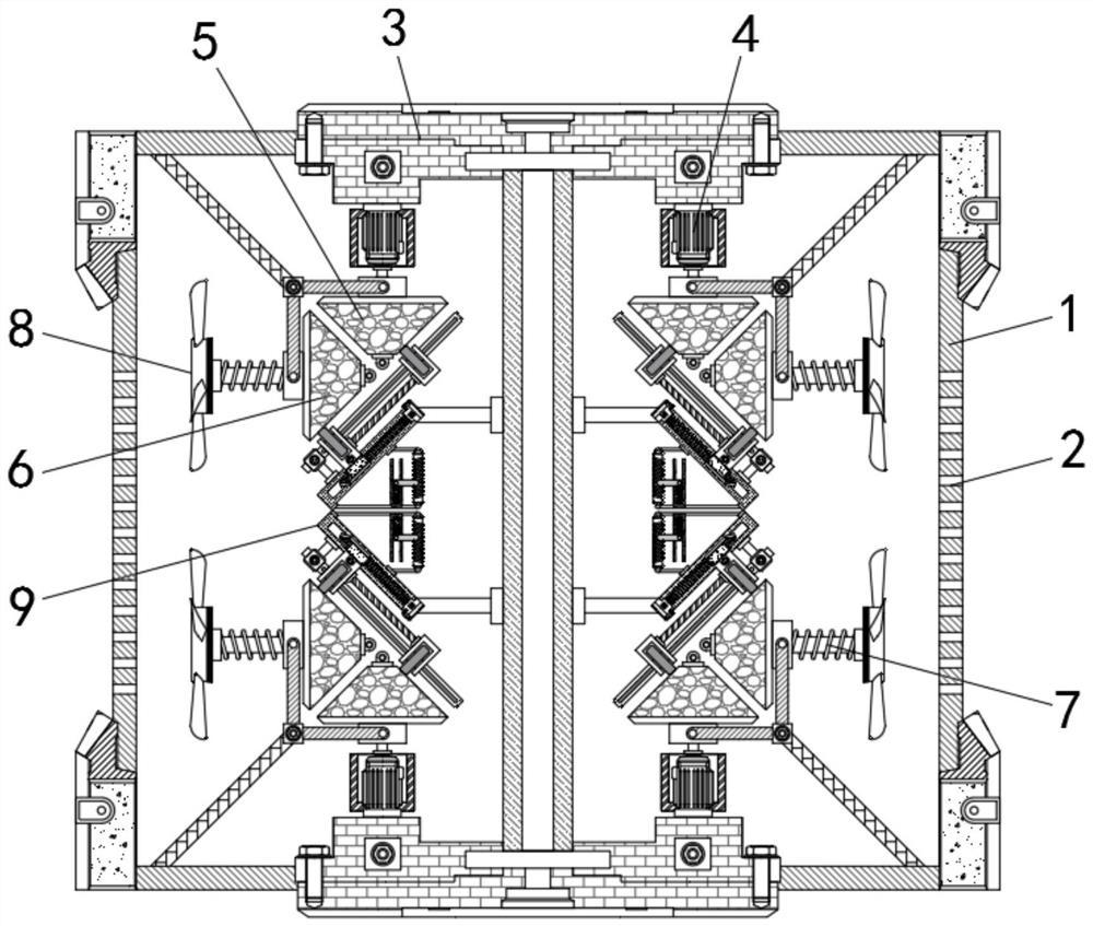
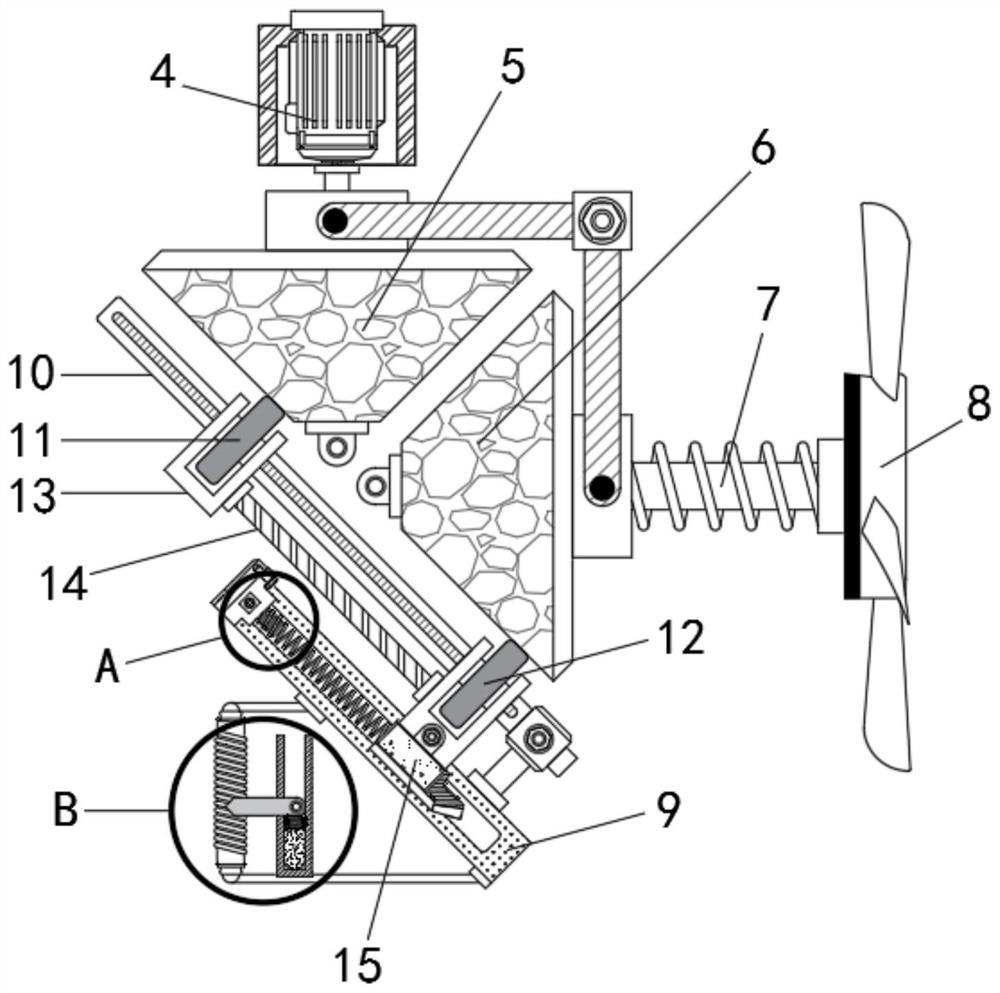
[0023] see Figure 1-4 , an automatically adjustable heat sink for an air purifier, comprising a device main body 1, a cooling hole 2 is opened on the side wall of the device main body 1, and mounting brackets 3 are fixedly connected to the upper and lower ends of the device main body 1, and the mounting bracket 3 is close to One end inside the equipment main body 1 is fixedly connected with a motor 4, the output end of the motor 4 is fixedly connected with a ...


PUM


Abstract

The invention relates to the technical field of air purification, and discloses an automatically adjustable heat dissipation device for an air purifier. The heat dissipation device comprises an equipment main body; heat dissipation holes are formed in the side wall of the equipment main body; and the upper end and the lower end of the equipment main body are each fixedly connected with a mounting support. According to the automatically adjustable heat dissipation device for the air purifier, when the inner temperature of the equipment rises, an air bag expands and drives a metal sliding sheet to slide along a resistance coil to make current in a circuit increased, and then the magnetism of an electromagnet is enhanced and a metal sliding block is attracted to drive a second friction wheel and a first friction wheel to synchronously move, and then, the rotating speed of the first friction wheel and the second friction wheel increases, and the rotating speed of a second conical wheel increases therewith and the fan is driven by a connecting rod to rotate at a high speed, and accordingly air flow in the equipment is accelerated, so that heat is rapidly discharged from the heat dissipation holes, the heat dissipation efficiency is improved, and the rotating speed of a motor is constant, so that excessive energy consumption is avoided, and the energy-saving and environment-friendly effects are achieved.

Description

technical field [0001] The invention relates to the technical field of air purification, in particular to an automatically adjustable heat dissipation device for an air purifier. Background technique [0002] Air purifiers, also known as air cleaners, refer to products that can absorb, decompose or transform various air pollutants and effectively improve air cleanliness. They are widely used in homes, factories, offices and other places. After working for a long time, the air purifier will generate a lot of heat inside, so it needs to be dissipated. Existing equipment generally uses fans to dissipate heat, but the fan speed cannot be adjusted, which will cause discomfort when the temperature is not high. Necessary energy waste, and will cause unnecessary wear and tear on the parts, shorten the service life, and cannot dissipate heat in time when the temperature is too high, which will cause the electronic components inside the machine to heat up, affect its stable operation,...

Claims


Application Information

Patent Timeline
IPC IPC(8): F24F13/00F24F13/20F24F11/89F25D17/06
CPCF24F13/00F24F11/89F24F13/20F25D17/06F24F2013/205
Inventor 陈应美
Owner 成都应晴白商贸有限公司
Features
  • R&D
  • Intellectual Property
  • Life Sciences
  • Materials
  • Tech Scout
  • Unparalleled Data Quality
  • Higher Quality Content
  • 60% Fewer Hallucinations
Learn More