
Laser reflecting plate positioning method based on corner joint feature structural body

A technology of laser reflection and positioning method, which is applied in two-dimensional position/channel control, vehicle position/route/altitude control, instruments and other directions, and can solve problems such as high constraint requirements of unequal side lengths, incorrect matching, and failure of positioning and navigation.

Active Publication Date: 2021-05-18
深圳易行机器人有限公司
View PDF5 Cites 1 Cited by
  • Summary
  • Abstract
  • Description
  • Claims
  • Application Information

AI Technical Summary

Problems solved by technology

However, the reflector data association based on the continuous field search method needs to ensure the accuracy of the initial pose estimation of the AGV, and the reflector data association based on the reflector side length characteristics has high requirements for the side length unequal constraints arranged between the reflectors. In some occasions, it is easy to cause wrong matching due to too uniform arrangement of reflectors, resulting in failure of positioning and navigation

Method used


Image

  • Laser reflecting plate positioning method based on corner joint feature structural body
  • Laser reflecting plate positioning method based on corner joint feature structural body
  • Laser reflecting plate positioning method based on corner joint feature structural body

Examples


Embodiment Construction

[0023] In order to enable those skilled in the art to better understand the solution of the present application, the technical solution in the embodiment of the application will be clearly and completely described below in conjunction with the accompanying drawings in the embodiment of the application. Obviously, the described embodiment is only It is an embodiment of a part of the application, but not all of the embodiments. Based on the embodiments in this application, all other embodiments obtained by persons of ordinary skill in the art without creative efforts shall fall within the scope of protection of this application.

[0024] It should be noted that the terms "first" and "second" in the description and claims of the present application and the above drawings are used to distinguish similar objects, but not necessarily used to describe a specific sequence or sequence. It should be understood that the data so used may be interchanged under appropriate circumstances for...


PUM


Abstract

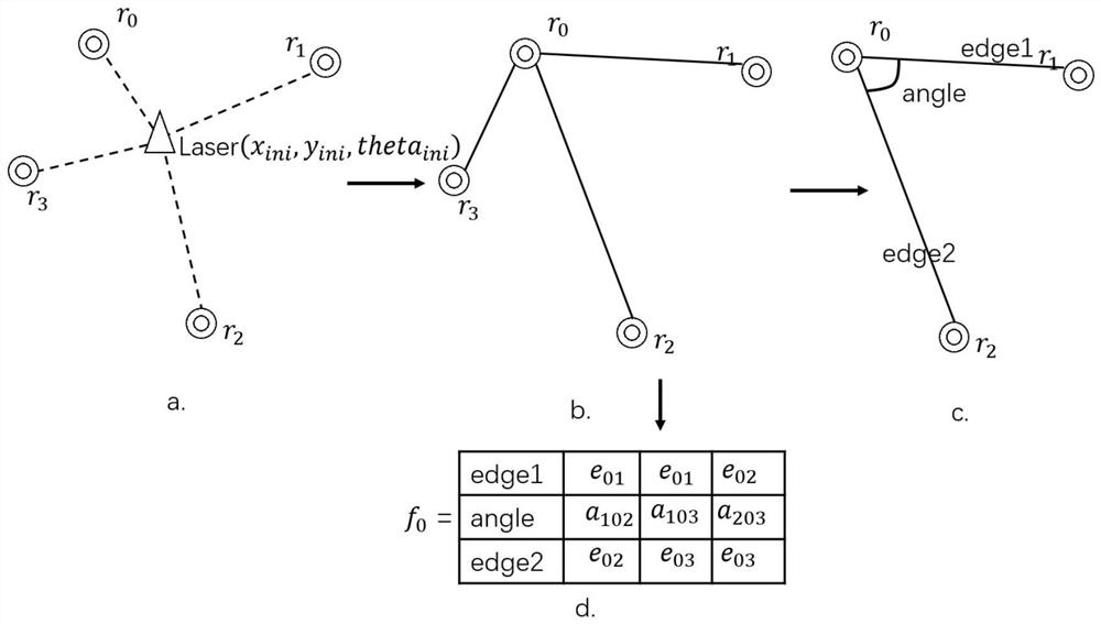
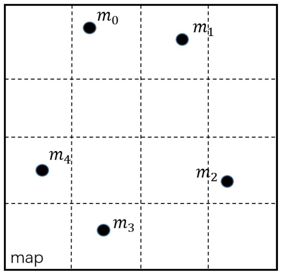
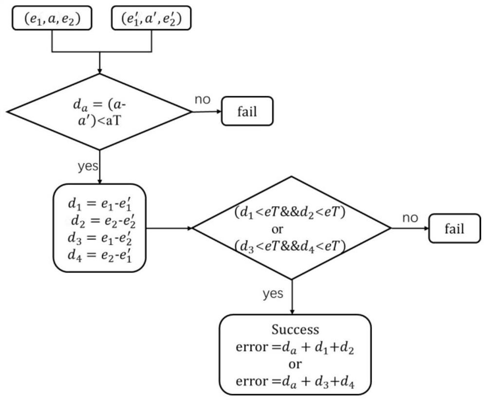
The invention discloses a laser reflecting plate positioning method based on a corner joint feature structural body. The method comprises the following steps of firstly, processing laser reflecting plate data, extracting and generating a corner feature structural body set of each reflecting plate, and matching the reflecting plates in a laser with the reflecting plates on a map one by one through a corner feature matching method; judging whether matching succeeds or not according to a set matching threshold value, and sorting matched pairing point sets according to matching results from optimal to subordinate; then carrying out pairing uniqueness detection on an obtained reflecting plate pairing point set sorting result, removing pairing of the reflecting plates with repeated participation, and taking the optimal first three groups of reflecting plate pairing points as data for subsequent geometric matching; and finally, accurately converting and positioning the initial estimated pose of a laser sensor into an accurate pose on a map through plane coordinate conversion by utilizing the obtained three groups of laser reflecting plates and map reference landmark two-dimensional coordinates in one-to-one correspondence, thereby completing accurate positioning of the reflecting plates.

Description

technical field [0001] The present application relates to a positioning method, in particular to a positioning method of a laser reflector based on a joint feature structure of corners. Background technique [0002] With the continuous application of automatic guided vehicles (AGVs) in the entire factory automated production, transportation, warehousing and logistics industries, the navigation technology of AGVs is becoming more and more important. At present, the navigation technologies used in AGV mainly include magnetic navigation, laser navigation, and visual navigation. Among them, laser navigation is a navigation technology solution that has been rapidly popularized in recent years. Due to its high-precision characteristics and environmental protection It has many advantages, such as lower requirements for transformation, more convenient construction than magnetic navigation, and higher stability and accuracy than current visual navigation, and has gradually become the...

Claims


Application Information

Patent Timeline
IPC IPC(8): G01C21/20G05D1/02
CPCG01C21/20G05D1/0219G05D1/0236
Inventor 徐冬云
Owner 深圳易行机器人有限公司
Learn More