
Automatic voltage control method based on active power trend judgment

An automatic voltage and control method technology, applied in AC network voltage adjustment, reactive power compensation, circuit devices, etc., can solve problems affecting the safe and stable operation of the power grid, large fluctuations in power grid voltage, and repeated switching of reactive power equipment.

Active Publication Date: 2021-05-18
XINZHOU POWER SUPPLY COMPANY STATE GRID SHANXI ELECTRIC POWER
View PDF11 Cites 0 Cited by
  • Summary
  • Abstract
  • Description
  • Claims
  • Application Information

AI Technical Summary

Problems solved by technology

In the power system, especially in areas where new energy installed capacity accounts for a large proportion, changes in active power will produce large and rapid changes, which will lead to large fluctuations in grid voltage
The traditional AVC control method simply follows the reactive device control strategy generated by the reactive voltage at a single moment. When the grid load changes greatly, it may not be able to quickly adjust the voltage to a reasonable range at first, and it will also cause the reactive device to fail. Repeated switching will not only cause economic losses due to the short life of the equipment, but also cause large fluctuations in voltage changes, which will affect the safe and stable operation of the power grid.

Method used


Image

  • Automatic voltage control method based on active power trend judgment
  • Automatic voltage control method based on active power trend judgment
  • Automatic voltage control method based on active power trend judgment

Examples


Embodiment Construction

[0030]A automatic voltage control method based on an active trend determined by the present invention includes the following steps:

[0031]1) Pre-set the time T of the current trend forecast daily;

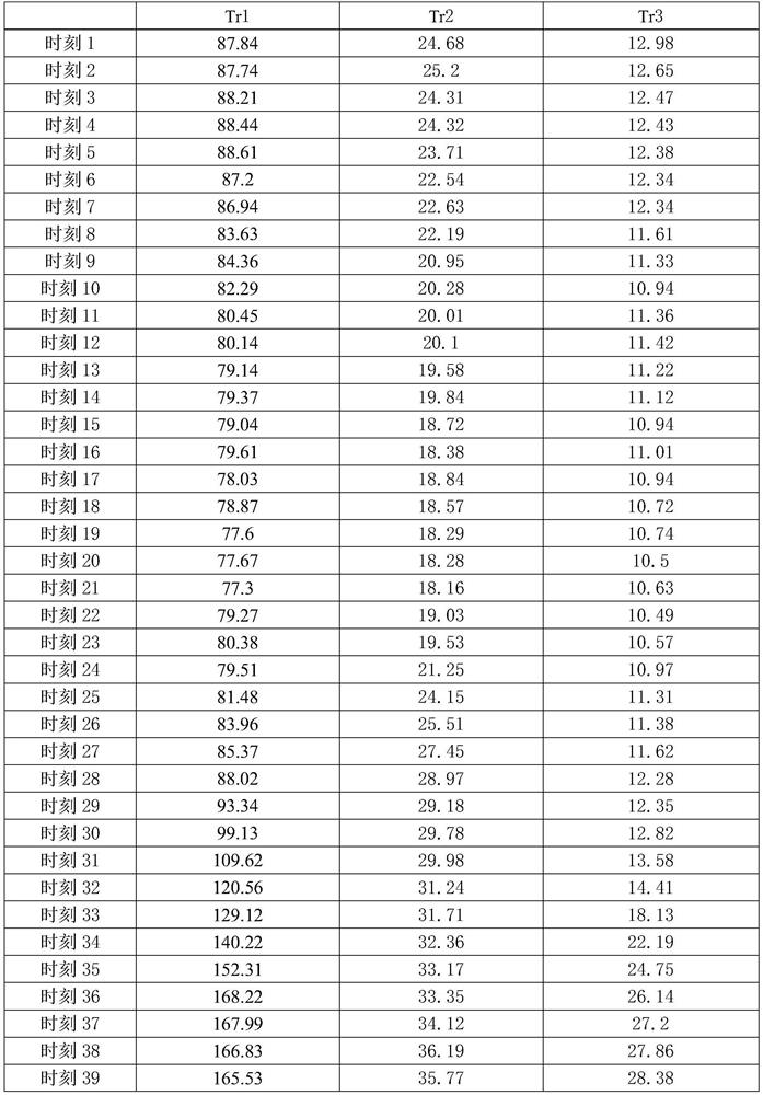
[0032]2) When the daily T is coming, according to the recent grid model, the readings are predicted by various types of programs, according to 15 minutes interval, calculate the results of the trend forecast for recent days ago, read the second There are all moments of each moment of each main change high voltage side winding, form a collectionIndicates that all the high-pressure power collections of all M-mainstall high-pressure side windings, whereOn behalf of the i-th mainly high voltage side winding, there is a powerful power data set, of whichRepresents the active power value of the i-th mainx high-voltage side windings at the X = 1, 2, 3, ..., 96, i = 1, 2, 3, ..., M;

[0033]In the present invention, Lin Yi is adopted when calculating the current trend, Sun Hongbin is "automatic generati...


PUM


Abstract

The invention provides an automatic voltage control method based on active power trend judgment, and belongs to the technical field of automatic voltage control of a power system. The method comprises the following steps: obtaining a day-ahead power flow forecast result, and calculating active power values of all transformer substations at all moments in the whole day through active power values of all main transformer high-voltage side windings at all moments in the next day; then, according to the all-day active power change trend of each transformer substation, establishing a priority action time period set of the transformer substation in the next day; and when the automatic voltage control cycle of the next day arrives, if the current moment belongs to the priority action time period set under the condition that the voltage of the transformer substation does not exceed the limit, formulating an optimization strategy for switching the discrete reactive power equipment by the transformer substation according to the load change condition of the time period. The method realizes the prevention and control of the voltage of the transformer substation, avoids the repeated switching of discrete reactive power equipment in the transformer substation in a rapid load change period, reduces the fluctuation amplitude of the voltage, and improves the voltage stability and voltage quality of a power grid.

Description

Technical field[0001]The present invention belongs to the field of automatic voltage control technology of power systems, and in particular, the present invention relates to an automatic voltage control method based on active trend determination.Background technique[0002]Automatic voltage control (hereinafter referred to as AVC, Automatic Voltage Control) is an important means of implementing power transmission network security (improved voltage stability margin), economic (reducing network loss), high quality (increasing voltage pass rate) operation. The AVC system architecture is above the grid energy management system (EMS), which can use the transmission network to run data. From the perspective of the global optimization of the transmission network, the best reactive voltage adjustment plan, automatically issued to power plants, substations, and subordinate The power grid dispatching body is implemented. Sun Hongbin, Zhang Biming, Guo Qing came to "Optimization of Earth Voltage...

Claims


Application Information

Patent Timeline
IPC IPC(8): H02J3/16
CPCH02J3/16H02J2203/20Y02E40/30
Inventor 郭亮王建平高马平吕晨旭李庆良李万林黄少波张斌
Owner XINZHOU POWER SUPPLY COMPANY STATE GRID SHANXI ELECTRIC POWER
Learn More