

Fan-shaped eccentric block force converter for vibration motor and vibration motor
A vibrating motor and movable eccentric block technology, applied in electrical components, electromechanical devices, electric components, etc., can solve the problems of high requirements on machining accuracy and roughness of cylinders and plungers, environmental pollution, and high sealing requirements.
- Summary
- Abstract
- Description
- Claims
- Application Information
AI Technical Summary
Problems solved by technology
Method used
Image

Examples
Embodiment 1
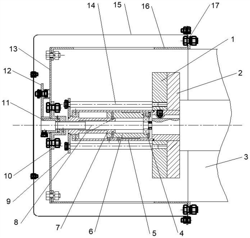
[0035] refer to figure 1 , the vibration motor 3 proposed by the present invention uses a fan-shaped eccentric block force converter and a vibration motor 3, including:
[0036] A connecting sleeve 5 is connected circumferentially with the shaft end of the main shaft of the vibration motor 3 by a key, and rotates synchronously with the main shaft of the vibration motor 3;
[0037] A fixed eccentric block 2 and a movable eccentric block 1 are sleeved on the connecting sleeve 5, the fixed eccentric block 2 is fixedly arranged on the side of the connecting sleeve 5 close to the vibration motor 3, and the movable eccentric The block 1 is located on the side of the fixed eccentric block 2 away from the vibration motor 3 and is in clearance fit with the connecting sleeve 5;
[0038] A sliding core 6 is arranged in the connecting sleeve 5, the sliding core 6 rotates synchronously with the connecting sleeve 5, and can be axially displaced relative to the connecting sleeve 5; specific...
Embodiment 2
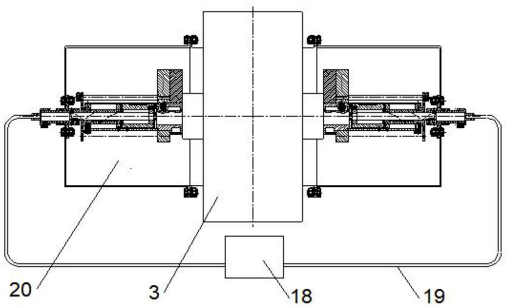
[0052] refer to figure 2 The vibration motor proposed by the present invention includes the force converter 20 as described in Embodiment 1, and the force converter 20 is symmetrically arranged on both sides of the vibration motor 3 . The pull shaft sleeve 11 of the torque converter 20 controls its rotation through the handle 12 fixedly connected with it. The handle 12 can be fixed on the supporting circular plate 13 by a locking bolt to fix the eccentricity. The locking bolt can keep the movable eccentric wheel 1 Set position, until it is adjusted again, then loosen the locking bolt. A dial for determining the angle of rotation of the handle 12 is also included. When the pulling bearing 11 on one side is adjusted to a suitable angle, the dial will display the rotation angle of the handle 12, and then the pulling bearing 11 on the other side can be directly rotated to the angle.
Embodiment 3
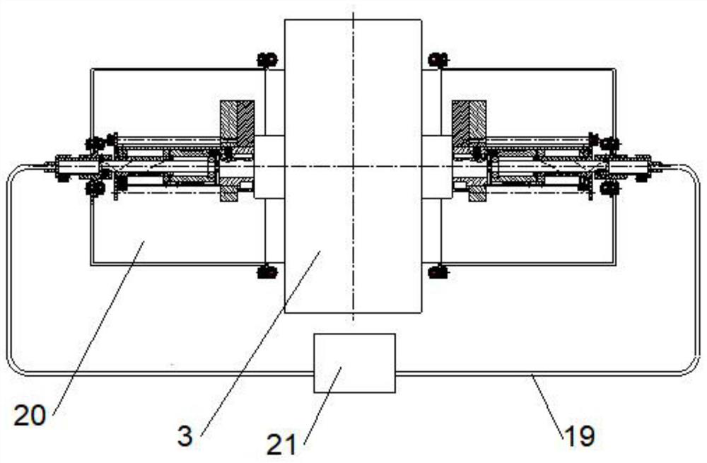
[0054] refer to image 3 , The vibration motor proposed by the present invention includes the force converter 20 as described in Embodiment 1, and the force converter 20 is symmetrically arranged at both ends of the main shaft of the vibration motor 3 . The rotation of the pulling bushing 11 of the force converter 20 is controlled by a manual torque converter 18 , and the manual torque converter is connected with the pulling bushing through a flexible shaft 19 . The pull bushings on both sides of the vibration motor are adjusted by direct synchronization with a manual torque converter.
PUM
 Abstract
Description
Claims
Application Information