Supercharge Your Innovation With Domain-Expert AI Agents!

Pile driving mechanism and pile driver

A technology for pile drivers and hangers, which is applied in sheet pile walls, foundation structure engineering, construction, etc., and can solve the problems of low equivalent force, high bearing reliability, gearbox lubricating oil, etc.

Pending Publication Date: 2021-05-07
SHANDONG LINGONG CONSTR MACHINERY
View PDF0 Cites 1 Cited by
  • Summary
  • Abstract
  • Description
  • Claims
  • Application Information

AI Technical Summary

Problems solved by technology

However, in actual production, due to manufacturing deviations, assembly deviations, etc., it is difficult to ensure that the vibration eccentric shaft is completely symmetrical and the eccentricity of the vibration eccentric shaft is equal. The high-speed rotation of the vibration eccentric shaft has high requirements for bearing reliability and gearbox lubricating oil.
At the same time, the exciting force generated by the vibrating eccentric shaft is superimposed in the vertical direction, but the exciting force in the vertical direction is a periodic sine wave, the effective force of the exciting force has periodic changes, and the equivalent force is lower than the maximum exciting force. Vibration force

Method used


Image

  • Pile driving mechanism and pile driver
  • Pile driving mechanism and pile driver
  • Pile driving mechanism and pile driver

Examples


Embodiment 1

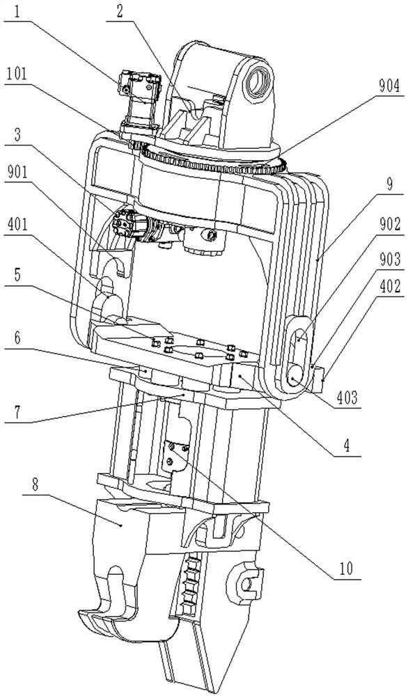
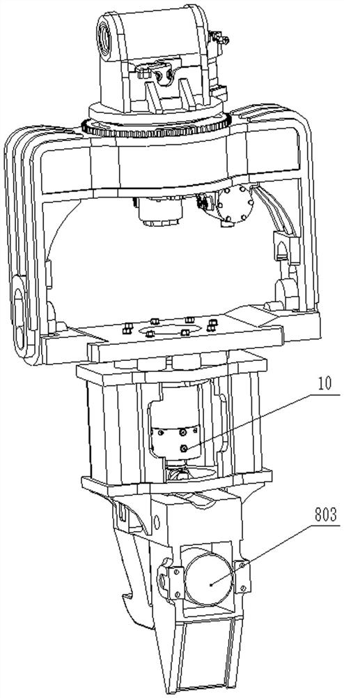
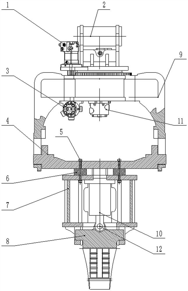
[0028] Embodiment one: if figure 1 and figure 2 As shown, the piling mechanism includes a hanger 9, a hydraulic cylinder 10, a fixed box 7 and a clamping hammer 8, and the bottom of the hanger 9 is equipped with a fixed box 7 that can move up and down, and one end of the hydraulic cylinder 10 is connected with the fixed box 7. The other end of the cylinder 10 is connected with the clamping tup 8, the two sides of the clamping tup 8 are respectively provided with a limiter 802, and the bottom of the fixed box 7 is provided with a chute 702 cooperating with the limiter 802 and with the clamping The limit plate 701 matched with both sides of the hammerhead 8 is a rib plate.

[0029] Such as Figure 5 and Figure 6 As shown, the clamping tup 8 includes a fixedly connected tup body 805 and a clamping plate 806, a clamping hydraulic cylinder 803 is provided between the tup body 805 and the clamping plate 806, and a limiting block 1 802 is arranged on On both sides of the hammer...

Embodiment 2

[0032] Embodiment 2: a rotatable support frame 2 is provided above the hanger 9, a drive motor 1 is installed on the support frame 2, a gear 101 is provided on the output shaft of the drive motor 1, and a fixedly connected rotary shaft is provided on the hanger 9. The ring gear 904 , the gear 101 meshes with the rotary ring gear 904 . The hydraulic oil drives the gear 101 of the output shaft of the drive motor 1 to rotate, thereby rotating through the slewing ring gear 904 on the meshing hanger 9, and then driving the relative rotation of the hanger 9 and the support frame 2, thereby passing through the fixed plate 4 and the shock absorber. 6 drives the fixed box 7 and the clamping hammer head 8 to rotate, and realizes the adjustment of the rotation angle of the clamping hammer head 8, so as to facilitate the angle adjustment of the clamping hammer head 8 and the pile 19 in the process of picking up piles, hanging piles and piles, and is convenient for operation construction. ...

Embodiment 3

[0037] Embodiment three: as Figure 7 As shown, the pile driver includes a pile driver body 12, a boom 14, a middle arm 16 and a small arm 18. The pile driver body 12 is mounted on the frame and the boom 14 is hinged, and the two ends of the middle arm 16 are respectively hinged with the boom 14 and one end of the small arm 18. , the other end of the small arm 18 is provided with the piling mechanism described in Embodiment 2; the small arm 18 is connected to the support frame 2, and the first oil cylinder 13 is arranged between the upper frame of the piling machine body 12 and the large arm 14, and the large arm 14 and A second oil cylinder 15 is arranged between the middle arms 16 , and a third oil cylinder 17 is arranged between the middle arm 16 and the small arm 18 .

[0038] When the present invention is in use, it is used in conjunction with a crawler excavator. During work, the pile 19 is fixed between the pressing plates 804 on the clamping hammer head 8 through the c...


PUM


Abstract

The invention discloses a piling mechanism and a piling machine, and belongs to the field of engineering machinery. The piling mechanism mainly comprises a hydraulic cylinder, a fixing box and a clamping hammer head, one end of the hydraulic cylinder is connected with the fixing box, the other end of the hydraulic cylinder is connected with the clamping hammer head, first limiting blocks are arranged on the two sides of the clamping hammer head correspondingly, and first sliding grooves matched with the first limiting blocks and limiting plates matched with the two side faces of the clamping hammer head are arranged at the bottom of the fixing box. The piling mechanism is convenient to machine, manufacture and assemble, only vertical force is generated during impact vibration, horizontal force does not exist, the impact frequency and the impact force are adjustable, and the use cost is low. The piling machine is mainly used for piling.

Description

technical field [0001] The invention belongs to the field of construction machinery, and in particular relates to a piling mechanism and a piling machine thereof. Background technique [0002] The pile driver modified based on the crawler excavator uses the high-speed rotation of the eccentric mechanism of the hammer head to generate a periodic exciting force, thereby generating high-frequency vibration, and transmitting the vibration to the pile body through the clamping part of the hammer head. , The soil structure around the pile changes due to vibration, the soil around the pile body liquefies, the structure between soil particles is disordered, and the instantaneous strength is reduced, resulting in the "fluidization" phenomenon of the soil structure. In this way, the friction between the pile and the soil is reduced, and then the pile is driven into the soil with the joint force of the excavator's downforce, the pile driver and the pile's own weight. [0003] The exis...

Claims


Application Information

Patent Timeline
Patent Type & Authority Applications(China)
IPC IPC(8): E02D7/18E02D11/00
CPCE02D7/18E02D11/00
Inventor 苗国华迟峰王永刘淑强
Owner SHANDONG LINGONG CONSTR MACHINERY
Features
  • R&D
  • Intellectual Property
  • Life Sciences
  • Materials
  • Tech Scout
  • Unparalleled Data Quality
  • Higher Quality Content
  • 60% Fewer Hallucinations
Learn More