
Light source device and light path switch thereof

An optical circuit switch and optical circuit technology, which is applied in the direction of motor generator control, control system, electrical components, etc., can solve the problems of jitter, subdivision driving cannot be applied to miniaturized optical circuits, and affecting the light blocking effect.

Active Publication Date: 2021-05-18
杭州微伽量子科技有限公司
View PDF4 Cites 0 Cited by
  • Summary
  • Abstract
  • Description
  • Claims
  • Application Information

AI Technical Summary

Problems solved by technology

It is common that the moment of inertia of the stepping motor rotor of this volume is less than 10 gm^2, while the moment of inertia of the light blocking sheet is greater than that of the stepping motor rotor itself. In this way, when the moment of inertia of the light blocking sheet is too large, the traditional fine The split-drive gait will cause the jitter caused by the inertia to continue to move forward after the light baffle reaches the designated position
For example: for a common 20-step stepper motor that meets the volume requirements (18 degrees for a single step, the torque is about 1mNm), after installing the light barrier, the single-step step time is about 4ms, and the time for two steps to 36 degrees It is about 6ms, but due to the inertia, it will swing back and forth around this angle, and the final stop time is about 100ms. The maximum angle of the initial overshoot can reach more than 18 degrees. Overshoot will affect the light blocking effect. Generally, the mechanical shutter can respond quickly. The shape of the designed light barrier is slightly larger than the spot size, and once the overshoot exceeds 2°-3°, it cannot be turned off, so the traditional subdivision driver cannot be applied to the miniaturized optical path that requires fast optical switches

Method used


Image

  • Light source device and light path switch thereof
  • Light source device and light path switch thereof
  • Light source device and light path switch thereof

Examples


Embodiment Construction

[0043] The present invention will be further described below in conjunction with the accompanying drawings and embodiments.

[0044] It should be pointed out that the following detailed description is exemplary and intended to provide further explanation to the present application. Unless defined otherwise, all technical and scientific terms used herein have the same meaning as commonly understood by one of ordinary skill in the art to which this application belongs.

[0045] It should be noted that the terminology used here is only for describing specific implementations, and is not intended to limit the exemplary implementations according to the present application. As used herein, unless the context clearly dictates otherwise, the singular is intended to include the plural, and it should also be understood that when the terms "comprising" and / or "comprising" are used in this specification, they mean There are features, steps, operations, means, components and / or combinations...


PUM


Abstract

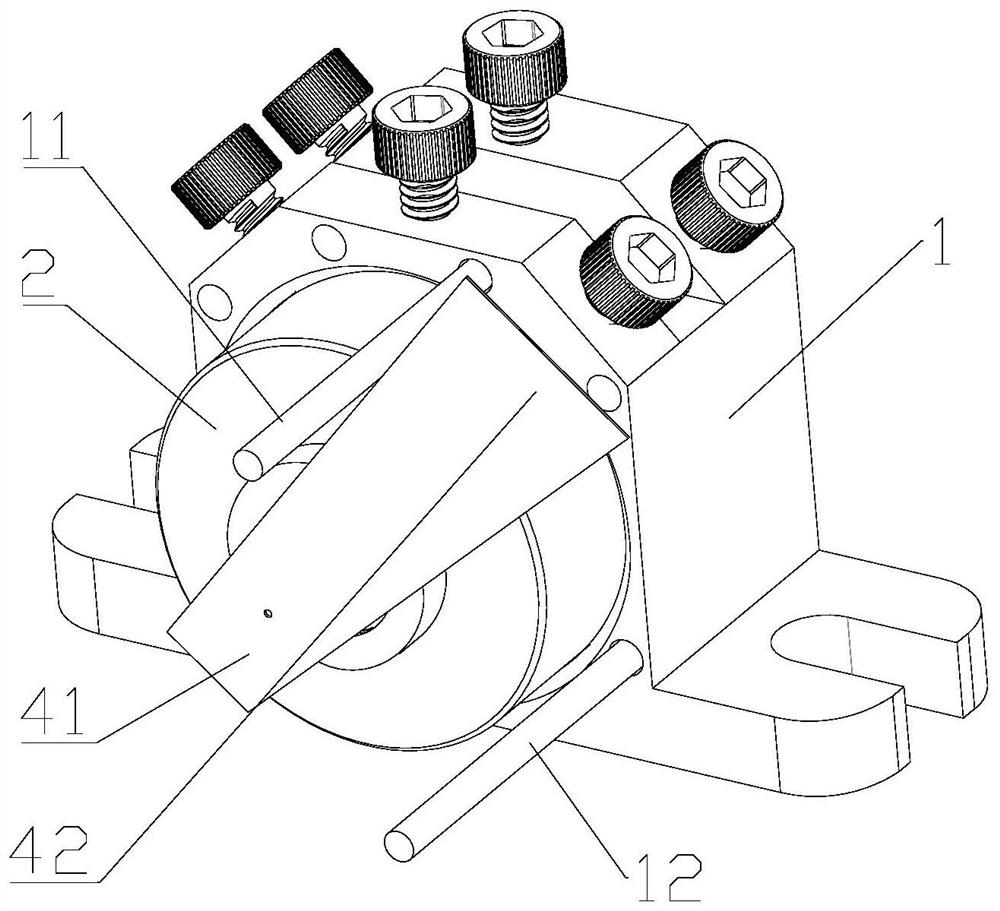
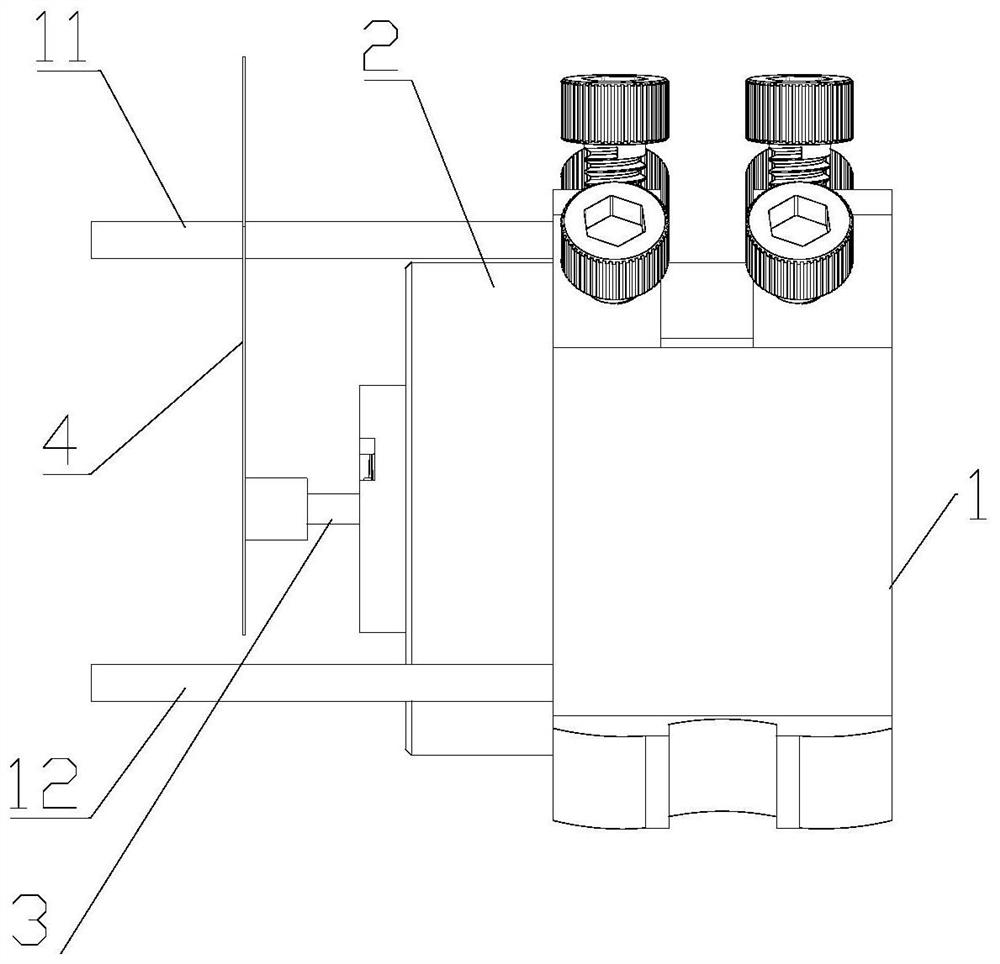
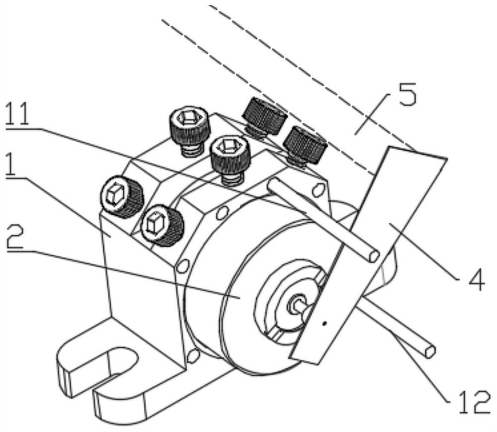
The invention discloses a light source device and a light path switch, the light path switch comprises a power supply, a control assembly and an execution assembly, the power supply, the control assembly and the execution assembly are connected with one another, the execution assembly is arranged on one side of a light path and comprises a light blocking part and a stepping motor, and the stepping motor is connected with the light blocking part and used for driving the light blocking part to rotate so as to open or close the light path; the light blocking part is provided with a fixed end and a movable end, the fixed end is connected with the output end of the stepping motor, and the movable end extends outwards in a certain radial direction of the stepping motor to form a light blocking part; the stepping motor comprises a rotor, a first winding and a second winding, the first winding and the second winding are at least arranged in the certain circumferential direction of the outer side of the rotor, the control assembly is connected with the first winding and the second winding, and the stepping motor is driven to rotate by controlling the direction and the magnitude of currents in the first winding and the second winding. Therefore, the light blocking part is driven to rotate so as to enable the light blocking part to block or avoid light rays. The light path switch has the advantages of high switching speed and low power consumption.

Description

technical field [0001] The invention relates to an optical path switch, in particular to an optical path switch and a light source device having the same. Background technique [0002] The optical path switch is generally used in the switch control of the laser beam. By rotating the shutter to the designated position, the beam can be completely turned off, so as to achieve the controllable switch of the beam in the optical path. With the miniaturization of the optical path, the mechanical shutter generally needs to have the characteristics of small size, low noise, fast response, and fast and accurate shutdown. [0003] The optical switch is usually composed of three parts: a light barrier, a stepping motor and a drive circuit. The function of the light blocking sheet is to block light. By fixing the light blocking sheet on the rotor of the stepping motor, when the rotor of the stepping motor rotates, the light blocking sheet is driven to rotate together, thereby realizing ...

Claims


Application Information

Patent Timeline
IPC IPC(8): H02P8/12H02P8/20
CPCH02P8/12H02P8/20
Inventor 罗顺烨郭彬邬黎明程冰俞佳俊周顺
Owner 杭州微伽量子科技有限公司
Learn More