[0047] In the various figures, identical parts are always provided with the same reference numerals, so they are usually also described only once. In particular, the drawings should be understood as representing various components or showing them in simplified form for greater clarity.
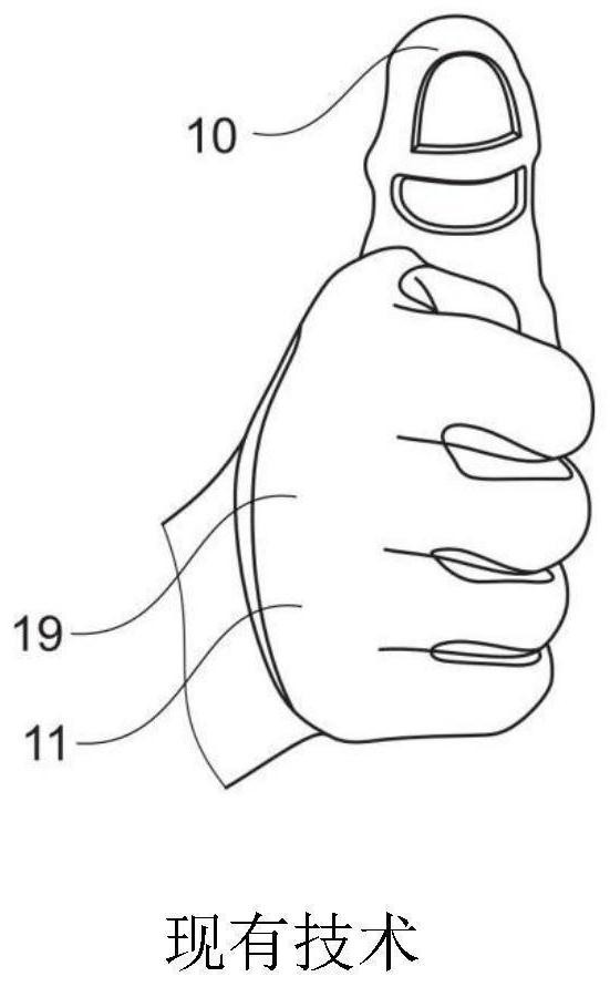
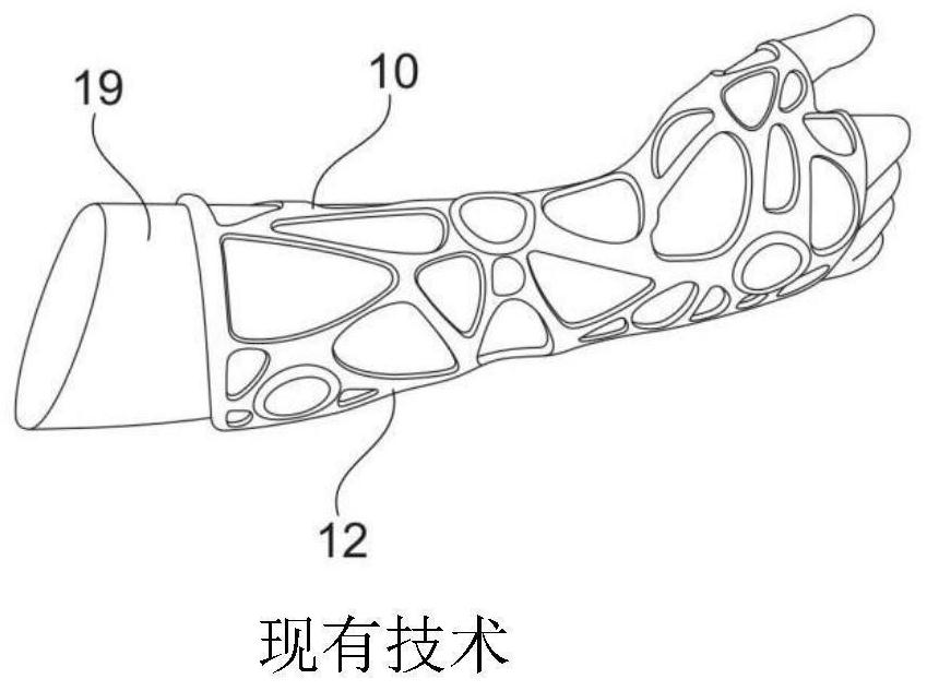
[0048] Figure 1a An orthosis 10 from the prior art is shown, which is designed as a thumb orthosis. The orthosis 10 is integrated into the glove 11 . The thumb orthosis protects the thumb joint of the user 19 during fitting operations that are performed very frequently and require a pressing movement of the thumb, for example. This reduces stress on the thumb joint. Figure 1b An orthosis 10 from the prior art is shown, which is designed as an exoskeleton 12 of the forearm and palm. Such an orthosis 10 can also be used for medical purposes, as well as an aid to assist the movements that are often performed especially in assembly operations, for example during continuous manufacturing on assembly lines in the automotive industry.
[0049] figure 2 An orthosis 10 according to the invention is shown (cf. Image 6 ) for the basic layout of the layers of the example. A first layer or fabric layer 2 is provided which comes into contact with the skin of the user 19 during use of the orthosis 10 (cf. Image 6 ), thus also allowing for a comfortable feeling when the intensity of work leads to sweating. A second or 3D printed layer 4 is applied on top of the fabric layer 2 . The 3D printing layer 4 has a plurality of printing layer elements 13 , wherein the printing layer elements 13 are designed as a plurality of elongated parts, ie pin-shaped or nail-shaped parts. The print layer element 13 has eg at least one surface element 14 for making contact with other objects and a connection element 15 for connecting the print layer element 13 to the fabric layer 2 . By geometrically forming the print layer elements 13, the user 19 (refer to Image 6 ) Certain movements using the orthosis 10 can be made harder or easier as desired. By arranging the surface elements 14 flush with each other, lateral movement of the print layer elements 13 relative to each other is made difficult. Through a gradual narrowing, i.e. a reduction in the cross-section from the surface element 14 to the connecting element 15, a space 16 is formed inside the 3D printed layer 4, wherein the space 16 allows the user 19 (cf. Image 6 ) required freedom of movement. In other words, the fabric layer 2 is preferably towards the user (cf. Image 6 ), while the 3D printed layer 4 (in particular its surface elements 14 ) faces the environment 25 of the orthosis 10 and forms the outer side 27 of the orthosis 10 . As can be seen from the illustrative embodiment shown by way of example, the surface elements 14 may be polygonal, preferably honeycomb-like, more preferably hexagonal.
[0050] Figure 3a A specific area arrangement of the 3D printed layer 4 on the fabric layer 2 is shown. Optionally, the 3D printed layer 4 can also be applied to the fabric layer 2 over the entire surface. For the production of orthoses 10 (reference Image 6 ), the profile 5 can be applied to the fabric layer 2. The fabric layer 2 can be cut along the profile 5 . By subsequently cutting the fabric layer 2 along the final profile 5 after the application of the 3D printing layer 4, the abrasion of the fabric layer 2 that occurs during the production method can be eliminated. Figure 3b Another specific area arrangement of the 3D printed layer 4 on the fabric layer 2 is shown, wherein the 3D printed layer 4 is formed at least partially from a metamaterial 6 . Such a metamaterial 6 can also elongate the textile layer 2 in the x-direction, eg during the expansion of the 3D printed layer 4 in the y-direction.
[0051] Figure 4 A further possible embodiment of a conceivable arrangement of the 3D printed layer 4 and the individual printed layer elements 13 on the textile layer 2 is shown. Depending on the design of the individual printed layer elements 13 , eg as pegs, rods or pyramids, different degrees of freedom (DOF) of the fabric layer 2 and thus of the orthosis 10 during use of the orthosis 10 can be achieved. The print layer elements 13 are designed with a constant rectangular cross-section starting from their surface elements 14 up to their connecting elements 15 (eg with respect to the drawn y-direction). Due to the constant cross-section and flush arrangement of the printing layer elements 13, there is no space 16 between the individual printing layer elements 13 in their starting position, ie in their non-bearing position. With this design, there is an allowable curvature 17 in the fabric layer 2, i.e. the fabric layer 2 faces outwards away from the user 19 (see Image 6 ) convex, ie in the direction towards the environment 25 of the orthosis 10 . As a result, the distance between the surface elements 14 of the individual print layer elements 13 increases, forming spaces 16 between the print layer elements 13 . Conversely, a convex movement in the opposite direction towards the inner side 26 constitutes an impermissible curvature 18 , wherein the impermissible curvature 18 of the fabric layer 2 towards the inner side (ie towards the user 19 ) is shown in dashed lines by the bars. Since the print layer elements 13 have no space 16 between their starting positions, there is also no freedom of movement for unwanted or impermissible curvatures 18 .
[0052] Figure 5a and Figure 5b A further possible embodiment of the arrangement of the 3D printed layer 4 on the fabric layer 2 is shown, wherein with a conical, pyramidal and/or tapered design of the individual printed layer elements 13, it is in principle possible to allow the fabric layer 2 to surround z Direction of the protrusion movement in two directions, namely towards the inner side 26 and towards the outer side 27 . The print layer elements 13 taper from their connecting elements 15 to their surface elements 14 (for example with respect to the positive direction of y drawn). Spaces 16 are thus formed between the print layer elements 13 . The fabric layer 2 protrudes outward around the z direction (i.e. in the environment 25 of the orthosis 10 (reference Image 6 During the movement in the direction of ), the gap 16 expands due to the increase in the distance between the individual surface elements 14 . During the inwardly convex movement of the textile layer 2 about the z-direction, the distance between the individual surface elements 14 and thus also the spacing 16 decreases. This raised movement can continue until the print layer elements 13 are connected to each other or are supported flush with each other. The maximum relief of the textile layer 2 can be set by the geometric design of the printing layer element 13 . according to Figure 5b Alternatively, the printing layer element 13 can also be designed in a shape that gradually narrows only with respect to the y-direction rather than with respect to the z-direction. as Figure 4 and Figure 5a Examples are combined. In this way, the individual print layer elements 13 are already flush or flat with respect to the z-direction and thus suppress the impermissible curvature 18 relative to the x-direction caused by the convex movement towards the inner side 26 . However, the curvature relative to the x-direction of the space 16 due to the convex movement towards the outer side 27 can still be achieved. In this way, each degree of freedom DOF can be different according to different directions.
[0053] Image 6 The orthosis 10 in the form of a glove 11 is shown worn on a user 19 . The glove 11 or orthosis 10 has an inner side 26 facing the user 19 (see Figure 4 ) and towards the outside 27 of the environment 25. In order to form the glove 11 as a digitized glove 11 , a corresponding application has already been incorporated in the production by 3D printing. To this end, the glove 11 can have various electronic components 7 . For example, a scanning device 9 for scanning barcodes, for example, can be provided in the glove 11 , wherein the scanning device 9 can also be actuated via a switching device 8 integrated in the glove 11 .
[0054] Figure 7 A method for producing an orthosis 10 according to the invention is shown (cf. Image 6) examples of production methods. The fabric layer 2 is provided 2a in the FFF/FDM 3D printer 1 by fixing the fabric layer 2 in the platform of the 3D printer 1 so that during printing operations 20, 22 (cf. Figure 8 ) to prevent the sliding of the fabric layer 2 during. A 3D printing material 3 is also provided 3 a by inserting the spool of wire 3 into the 3D printer 1 .
[0055] Figure 8 Shown is a production orthosis 10 (cf. Image 6 A flowchart of a method related to an example of a method of producing ). Initially 1a, 2a, 3a, 7a 3D printer 1, fabric layer 2, 3D printed material 3, and where appropriate further inserts, in particular non-3D printed electronic inserts 7, are provided. After inserting the fabric layer 2 into the 3D printer 1, in a first printing operation 20, a 3D printing material is applied to the fabric layer 2 to form a 3D printed layer 4 (cf. figure 2 ). Where appropriate, this first printing operation 20 can be interrupted by a pause 21 so that eg the electronics insert 7, the switching means 8, the scanning means 9 and, where appropriate, a further fabric layer 2 can be inserted. 3D printing then continues in a second 3D printing operation 22 . After the 3D printing operation 20, 22 is completed, the orthosis 10 can be removed 23 and finished 24 by finishing 24 the orthosis 10, for example by cutting the fabric layer 2 to follow the profile 5 (cf. Figure 3a ) size, and then prepare it by subsequent sewing.